• The move to the new server is done. There are some software and database maintenance updates in process. This has us passing the hat around to help out. We appreciate any donations. Seriously, even a dollar helps. The payment page may be found here - https://www.audiokarma.org/support.html

My Scott LK-72 Restoration -LONG Journey But Not There Yet

fredi898

New Member
Back around 1995 I saw a "Free" post in HP's internal ads for a Scott LK-72. Luckily I was the first to claim it (a gold-face, neatly built unit, in mostly pristine condition). It came with original instruction book and a note saying one of the 0.1 uf was leaking and needed replacement. As soon as I got home I hooked it up and listened for a while. I was glad it worked but it didn't quite sound "Hi-Fi". That was the start of this long journey.
Over the next 18 months I replaced most of the film and electrolytic caps that I could get (mail order, surplus stores) as well as resistors that were to be matched. Somehow in the process I took a detour thinking I could make use of the transformers to build a "minimalist" amp bypassing tone controls; improve voltage regulation, power sequencing, layout; adapt to more available output tubes, and to utilize often hyped-up components like silver hook up wires, gold plated RCA terminals, modern electrolytic caps etc.
All these craziness/foolishness came to a stop because of an oversea job assignment and all DIY projects had to be shelved and put in storages. Even after my return 10 year later I could not find the heart to revive this project. In the mean time my audio amplification went from Borbely DC-10 to a pair of single-end monoblocks, to a Pass A-5 clone currently used. This restoration wasn't even on the back burner.
Last September I accidentally stumbled upon this forum and my interest in the Scott amp got rekindled big time. I was truly impressed by the vast expert knowledge shared on this forum and inspired by many contributors' restoration experience. I would restart my restoration and make it my only amp if I could duplicate some of the successes discussed here.
This what I have done so far:
- Reinstalled the transformers (embassingly)
- Replaced the filament rectifier and the resistor string (1x39-ohms + 3X18-ohm)
- Restuffed can caps (with some careful surgery) with multiple modern electrolytic caps (105 Deg rated)
- Replace the grid return caps for the 7951 with 200K matched resistors
- Implemented bias voltage adjustment pots, but with 22K, instead of 10K resistor for the "tail".
- Added CL-80
- DeoxIT (D5) all pots, switches and sockets
- Checked all tube sockets ( after one loose 12AX7 socket pin (filament) caused some scares).
- Replace power cord and AC shunt cap
- Added 10-Ohm 1/4 watt current sensing cathode resistor for the 7951 tubes
- Bought new Tung-Sol 7951As to replace original (3 RCA and 1 Realistic (Radio Shack)?)
- Bought new 6U8 (Philips) to replace 6GH8s

Current State and Help! (:)
1. With AC Line set to 115 (via variac) to get B+ to 425V, I am not able to adjust the bias to get anywhere near the desired 35ma. Using the new TS 7951A and the pots dialed all the way to apply max bias voltage (-44V) at the center lug of the Bal pots, the cathode currents were around 60+ to 70 ma. With the old tubes I still get more than 40ma. I plan to try different bias voltages (from filament voltage drop resistor tabs) but I am a little confused how this can achieve the -18v bias voltage at the grid (pin 6) of the output tube.

2. I suspect the bais pots I used from what I had on hand are "audio taper". Wonder if I should change them to "linear". If so, does anyone know a source for10k pots with 6mm bushing? I am hoping not to enlarge the mount holes. Related to the pots, would 50K work just as well (the "tail" resistor would need to change too)?

Apologies for this LONG (first) post and Thanks in advance all any comments/suggestions.

Fred I
 
Register to hide this ad
Fred,
For bias, I have used 10K, 25K, 50K pots on various amps, stereo and guitar.
You would have to adjust the bias supply and/or tail resistors to work with the pots of your choice.
For my LK-72 which matches the LK-72B schematic I used these pots:
https://www.ebay.com/itm/10K-OHM-MI...905461&hash=item4d91f63683:g:9p4AAOSwqBJXVxWq
Very very nice pots. You pay $3.95 shipping for the total order so basically $4 per pot and $4 for shipping.
I bought two each of 50K and 100K for the Bias and Balance pots per the LK-72B schematic.
The original bias and balance pots were 3/8" bushing size. I put in the above pots which are 1/4" (6mm) bushings.

I recommend you leave the power tubes out and power up the LK-72 and get the bias voltage and range sorted out. I adjusted the tail resistor from 82K to 68K and now have -17 to -24 volts.

I wouldn't think audio taper would pose any problem, you just won't have a linear turns to voltage relationship.
Jef
 
Last edited:
Just did one of these myself, a long and tedious project as these are often kit-built and not very well built by the original owner, if that is your case you will need to go thru carefully to see if it is wired correctly. It seems you sure did all the right dances except change the death cap, add the diode trick to the rectifer, and 100 ohm screen safety resistors in the outputs.
 
Another note.....
My line voltage runs 122 typically. One CL-80 drops the voltage by 2.5v. That made my voltages pretty good. Pwr tube heaters are at 6.38vac. 5AR4 at 5.21. Preamp DC heater voltage set via the dropping resistor. All B+ voltages generally match the schematic, some dead on some not but all within 10%.
I just went thru it all within the past week.
Jef
 
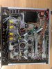
Thanks to all the quick replies and very helpful comments. Below shows most of the changes I have made. I felt the original builder did a very good job based on the quality of solder joints and routing of wires. The schematics that came with the instruction book shows Drawing Number D-LK-72-C Sub 3 (dated 10/18/60 with three revisions
dated 11/22/60, 9/14/61 and 7/27/62). I am afraid I don't know the if this is LK-72B or not. It does not have bias adjustment and the DC balance pots are 500K. If you need this Jef I can try posting a jpeg or scan. It's good to know where to get the small pots. Exactly what I was looking for.

As for the death cap, is it the 0.01 10KV cap across the primary? If so I have replaced it already. I have read about the 100 ohm screen safety resistors but not exactly sure
where they go. Would you please clarify dkargreen?

Thanks!
IMG_20190726_103126.jpg
 
Fred,
I think this is the schematic you mention above for your unit:
http://akdatabase.com/AKview/albums/userpics/10007/HH Scott LK-72 Schematic D-LK-72-C1 Sub 3.pdf

You have DC Balance pots only, it is always recommend to add Bias pots. My 1963 version LK-72 has Bias and Balance pots from the factory. To model after mine, I think all you would do is lift your existing -45v wires from the wipers of your 500K Balance pots and attach them to the ends of two new 50K pots. The other end of the 50K pots will connect to ground through a 82K resistor (I changed mine to 68K for -17 to -24v of bias). Then run the 50K wipers to your 500K wipers. Wire the 50K pots per this (Scott 1963 schematic):
http://akdatabase.com/AKview/albums/userpics/10007/HH Scott LK-72B Schematic D-LK72B-C1 Sub 0.pdf
Once you get the bias adjustment range correct, set it for max negative volts and install the power tubes. Then dial in your mA across the 10 ohm cathode sampling resistors.

Chuck, are you sure your Balance pot chassis holes are 1/4" and not 3/8?
I also recommend putting the grid resistors and caps back to stock Scott values. Then the correct -44v or so bias voltage should work as designed. I believe you can add in some 50K Bias pots to feed your factory 500K Balance pots as I explained above. You should strive to get all B+ , heater and bias voltages close to the schematic.
Jef
 
Last edited:
As to the 100 ohm screen resistor addition, what you do is disconnect the orange 380v wire daisy chaining between the 7591 tubes.
Then at the 7591 closet to the PT, disconnect the orange wire from pin 8 and connect it to pin 1. Now connect a daisy chain wire between all 7591 pins 1 so that you will have the 380v at each pin 1. Each 7591 already has a jumper between pins 4 and 8, it stays. Connect a 100 ohm 1/4w metal film resistor between pins 1 and 8. You can use 1/2 watt if you desire.
 
I happen to be in the middle of fine tuning my LK-72 which I restored 10 years ago.
One thing I you may want to do is replace the cap's behind the controls. That's if you want to go all the way with your unit. Mine included 4 ceramic caps in that area. I replaced 2 so far and they were WAY out of tolerance. I plan to replace the other 2 today
I replaced all the controls area resistors with metal film, 14 carbon comp were removed and checked. 7 were within 5% tolerance and the other 7 were between 5 and 10%. The worst was 9.8% deviation from the color band.
Just an FYI.
Jef
 
Thanks very much Jef and crispycircuit !!

Jef,
The first schematic you posted matches exactly what I have. I think the Bias adjustment circuit I added is similar to those shown in the Scott 1963 drawing, with the exception of 10k vs 50k pots and the value of the trailing resistor. Will definitely verify later (busy Sunday here :)).

From the 1963 schematic, I see -56V coming right off the preamp filament rectifier (through a 22k resistor), is tied to the "top" of the pair of 50K pots. The drawing seems to suggest -45 v at the wiper, from which they are connected to the wiper of the DC Bal pots (500k in my case). Am I correct in understanding that you are getting -17V to -24v swings at that point (DC Bal pot wiper) or at Pin 6 of the 7951 tubes?? With -44 V at the top of my 10K pots, currently I get between -36 to -44 v at the wiper. At Pin 6 of the 7951s, the bias voltages are between -12 to -15 volts.

WIll follow your suggestion to get the correct bias figured out next (trying different taps from the rectifier resistor string) with the output tubes removed, Following that I will add the grid stop resistors.

I have replaced the 4 ceramic caps behind the control panel shield. Hopefully I can get the amp working again first then check for other resistor values :).
Thanks again!
Fred
 
When I compare your schematic to my Lk-72 schematic, both are sending about -45v to the balance/bias ckt.
I figure you simply use your -45ish volts at your balance pots and run it to two the ends of two new 50K pots, wire the pots like my schematic. Take the wiper outputs of the new 50K's and connect to your 500K wipers. Done.

It shouldn't matter where in the heater/bias string of resistors we get the -45ish volts from. Your present -45v tap will work in a bias/balance 4 pot arrangement.

Yes, I have -17 to -24 volts at the 7951 tubes pin 6.
 
Chuck,
Here is a thread by Dave451 on his LK-72 restoration. If you look at post #77 you will see his sketch of the bias circuit he put in. You could use your existing -45v bias and do the same thing. Any of the threads/posts by Dave451 are worth paying attention to. I recommend you throughly read his LK-72 thread.
https://audiokarma.org/forums/index.php?threads/scott-lk-72-rehab.784404/page-4
There are so many different ways to build a bias ckt. You can use a wide ranging combination of pots and resistors.
As I previously mentioned, install and test the bias ckt without the power tubes.
New Tung-sols will need about -22v at pin 6.
Jef
 
Hi Jef,
The bias adjustment circuit I used was based on what Dave451 described.

I did just realize that with the grid resistor (connecting pin6 of the 7591s to ground) was changed from 330k to 200k, I was never going to get more than -14 volts there (-46 volts at the wiper of the 500k Bal Pot).
I read the original spec of 330k was said to be too high. I plan to change it to 300K and also increase the bias voltage to >46v. Would that be a good idea?
Thanks for the detailed description on how to add the 100 ohm screen resistors. I happen to have stolen pin 1 of the 7591s when adding the 10-ohm cathode resistors. I will need to figure out another way, should be doable.

Thanks,
Fred
 
Go look at post #4 of Dave451's thread (that I linked in post 14), dcgillespie addressed the changing of the 330K's.

Do you who Warren Buffett Is?
What Warren is to the financial world Dave Gillespie is to the tube world...............just sayin.

Messin with those grid reference resistors IS messin with the bias.....

You can probably ground those 10 resistors anywhere. You may have to make a ground buss out of 14awg solid wire to tie the resistors to.
Edit: Or keep pin 1 for your grounds and add the 100 screen resistors later and run a buss wire near the 4 tubes to carry the screen voltage.
 
Last edited:
Chuck,
Do you have your 7591 tube sockets pin #6 wired correctly?
The pic is fuzzy if I try n blow it up, can't tell for sure.

Edit: Cancel that. Looks ok.
 
Last edited:
Yes from what I have read on this forum so far, Mr. Gillespie is a very well respected guru. I should have read the many posts on Scott amps more thoroughly!
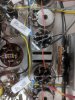
Here is a close-up of the wiring around the 7591s. The 200k resistor will be changed back 330k today.
Thanks!

IMG_20190726_103034.jpg
 
Looking good!
About the wires attached to pin 1 of each power tube, do they go to test points?

You will have a nice unit once done.
Jef
 
Back
Top Bottom