• The move to the new server is done. There are some software and database maintenance updates in process. This has us passing the hat around to help out. We appreciate any donations. Seriously, even a dollar helps. The payment page may be found here - https://www.audiokarma.org/support.html

My Yamaha CA-1000 Restoration / Modifications Thread

Parabellum27

Active Member
Hi there,

I have been posting a few threads and replies since I acquired my CA-1000 back in September 2018 about some restorations, modifications and upgrades. The purpose of this specific thread is to gather all the information I acquired in one place describing all steps, questions, answers, decisions I have made regarding the work made/to be made on my amplifier. Hopefully, this will serve as a source of inspiration for other users who wish to perform similars restorations / modifications. I wish share all the details and you are welcome contribute in any way. So here goes..

Some may find this silly, but my goal with this is to bring this amplifier back to life and beyond. I want to give it the best treatment possible (within reason) and I am curious to know how it will perform when connected to better DACs, interconnects, speaker cables and modern tweaks.
 
Last edited:
Register to hide this ad
This is my original thread back in Sept. 10, 2018:

http://audiokarma.org/forums/index....-1000-need-advices-for-future-project.837149/

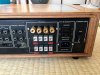
Again, here are the pictures of my amplifier when I got it. The wood case in damn close of being mint. All sharp corners, no dings, etc. There is only a slight discoloration in front of it from exposed sunlight I guess. I will remedy to that later this spring when the weather will be warm enough to work outside. Don't worry, I have no plan to strip the finish and sand. Most likely I am going to use Howard's restore-a-finish. That's for later.
 

Attachments

  • IMG_2919.JPG
    IMG_2919.JPG
    91.1 KB · Views: 202
  • IMG_2920.JPG
    IMG_2920.JPG
    74.8 KB · Views: 183
  • IMG_2921.JPG
    IMG_2921.JPG
    72.9 KB · Views: 174
I did a rebuild on the power supply micro switches and amplifier boards on mine a few years ago. Did not see going much deeper than that. New caps replace fuse resistors Zeners regulators that sorta things. Set to factory specs.

Left the speaker connections alone. They work good as they are IMO.
 
As I have explained in another thread, when I went to purchase the amplifier the speakers were tucked under a table sitting right next to eachothers so I didn't pay attention if the sound was coming from BOTH speakers. Well, they did not and I only found out when I plugged everything once home. Silly me. Well, this was my first vintage amplifier purchase and I had pretty much zero experience with this type of gear, and I was pretty excited to get my hands on this piece. Lesson learned.

I knew right from the start that I would need to upgrade the binding posts in order to be able to use my Kimber cables KS-3033. Probably back in these days, those 18 ga. were sufficing but things have evolved light years in audio, and I have those cables from a previous hi-fi setup so for sure I wish to use them. After searching the interwebz, I found a company, https://speaker-terminal.com/en/ to name it, that makes customs back plates for vintage amplifier. Since there was no product for the CA-1000, I contacted them thru the holidays and two weeks later, they sent my an e-mail telling me that they had made some for me and that they were up for ordering on their site. I ordered them right away. The quality is excellent by the way. This company is based in Germany so that says everything.

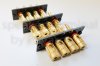
In my previous thread, I uploaded some pictures and the gurus here advised against installing them because they were made out of copper / brass and the distance between the binding post is very close. So I put this on hold for a while. You can see the actual product here.
 

Attachments

  • DSC_8307.JPG
    DSC_8307.JPG
    65.1 KB · Views: 162
  • Speaker-Terminal_YAMAHA-CR-1020-1.jpg
    Speaker-Terminal_YAMAHA-CR-1020-1.jpg
    190 KB · Views: 763
  • IMG_3155.JPG
    IMG_3155.JPG
    43 KB · Views: 156
Another thing that was plan right from the start was to do a full restorations, and repair since the right channel was out. Also, I did not mention but all the pots and switches were quite dirty and badly scratching. So, a full clean up was mandatory.

The big issue I had was to find the right guy to do the job. I know a few qualified technicians in Canada but I would have needed to ship the amp back and forth. I ruled that out because I was afraid of it being damaged during transportation. So I found someone locally. After exchanging quite a few e-mails and phone calls, I felt I had enough confidence in him to perform the work. Full recap was done. My tech was very specific about the right capacitors to use for this type of amplifier and he stressed that every capacitors had its purpose. My knowledge is limited when it comes to electronics so I have to rely on the pros (and that's what and why I pay for it, eh). The right channel was also fixed and I was glad that it could be fixed.

Part of the restoration was to change the two main capacitors. In this thread, I talk about this specific topic:

http://audiokarma.org/forums/index....ir-my-first-yammy.754511/page-5#post-12037191

So, Cornell-Dubilier capacitors were installed in lieu of the old ones. I don't have the specific part number on hand right now but I will dig this information so that you know which one was installed if you ever have to change them. You can see the work done in the picture attached. I will not bore you with all the other pictures of the recap as it is fairly standard.
 

Attachments

  • IMG_4220.JPG
    IMG_4220.JPG
    69.4 KB · Views: 188
  • Clamps_LI (2).jpg
    Clamps_LI (2).jpg
    57.2 KB · Views: 196
Last edited:
index.php
Just and opine. A lot of exposed metal surface so close together. Be extremely careful.
 
index.php
Just and opine. A lot of exposed metal surface so close together. Be extremely careful.

I remember you advised against it in my other thread. My tech also stressed to not install them because of that reason alone. So I gave up on using these. But, I didn't give up on the idea to find an alternative :). More on that later...
 
Last edited:
Another modification I wanted to be performed was to change the original lamp cord to a cable of much better quality. You can see all the information in this thread :

http://audiokarma.org/forums/index.php?threads/power-cord-upgrade-for-yamaha-ca-1000.838810/

A lot of discussion were held, lot of opinions and advice were shared. I thank everyone who contributed to this hot topic.

I raised this question at the time of the restoration so I was kind of short in time to make a final decision. I did not want to rush things up so I decided to focus on the restoration, repairs and cleaning telling myself I would come back later when my plans would be more clear.

Talking with a buddy of mine, he informed me of a very competent technician in Laval, Qc that operates a business (Planabox, if you ask). He enjoys a great reputation in the fields so I decided to contact him and see what could be done with the cable upgrade. After exchanging a few e-mails and phones calls, he suggested me that instead of installing a cable without knowing the sound signature that would potentially not match my amplifier, to install and AC/IEC socket. Woaaah.. I was open to the idea but I would need to make some study to see if it could work. And, I have to trust the guy...

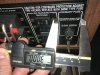
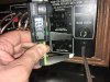
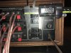
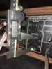
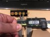
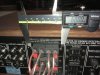
So, I grabbed a vernier caliper and started measuring to see where this could be fitted...

In the meantime, I did some research to see how it could look. You can see the last picture another CA-1000 (source : https://www.stereo.net.au/forums/topic/114174-fs-yamaha-ca-1000/ ) that, if I can qualify it bluntly, has been butchered to fit the AC/IEC socket. I find this solution, while I guess it is working, to be quite unelegant. For sure I did not want that to be this way, otherwise I would have forget about it.
 

Attachments

  • IMG_4110.JPG
    IMG_4110.JPG
    116.7 KB · Views: 217
  • IMG_4118.JPG
    IMG_4118.JPG
    102.3 KB · Views: 209
  • IMG_4120.JPG
    IMG_4120.JPG
    104.8 KB · Views: 207
  • IMG_4112.JPG
    IMG_4112.JPG
    104.5 KB · Views: 199
  • IMG_4115.JPG
    IMG_4115.JPG
    62.3 KB · Views: 206
  • CA-1000 Modifié.jpg
    CA-1000 Modifié.jpg
    105.3 KB · Views: 228
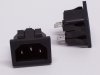
Continuing my research, I found that there are AC/IEC socket that do NOT have the screws by the side. Kind of snap in.

Relying on the schematics of the socket, I came to believe that it could potentially fit at the lower right corner of the back of the amp. That would replace the lamp cord altogheter. Two birds, one stone. So last week I went to Laval to drop the amplifier and have a chat with the owner explaining what I want/do not want. It took the whole week so that he had the time to open it but he confirmed me that it could be done. I stressed that I want that kind of modification, if done, to look stock from the company, as if it was designed to be that way. Again, he confirmed that it would look like original. So I gave the go...
 

Attachments

  • AC IEC DIMENSIONS.jpg
    AC IEC DIMENSIONS.jpg
    63.5 KB · Views: 99
  • 100_5537.jpg
    100_5537.jpg
    40.6 KB · Views: 100
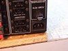
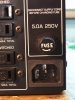
And here is the final result. I was amazed at his skills and the work done to say the least. Despite the fact that there is a ground pin in the AC/IEC socket, it is not connected inside. But still, by using any power cable, the ground would be useful anyway even if not connected inside (don't ask me why, I am no tech). Another thing I forgot to mention is that the fuse holder also has been changed for a brand new. The thing is that, in order to prevent interference with big IEC plugs, the idea was to install a fuse holder that does not protruded from the back of the casing. But what happened is that the hole for the original fuse holder on the CA-1000 was already too large for that type. He did however made sure that there would be no interference no matter the size of the plug. See photo 6622. The old fuse holder was corroded and the original fuse had its wire bent probably due from overheating. So, it made sense to change all this at the same time.

So, finally, another box is checked with this CA-1000. I can finally use the cable I want. I don't want to start the flaming debate of the cables but suffice to say that I am from of the believers. Not just marketing, by repeated listening sessions swapping power cables. It always made a change but I believe it is all a question of synergy with the other electronics.

Credits to www.planabox.com
 

Attachments

  • 100_6620.jpg
    100_6620.jpg
    85.3 KB · Views: 213
  • 100_6621.jpg
    100_6621.jpg
    55.8 KB · Views: 209
  • 100_6622.jpg
    100_6622.jpg
    47 KB · Views: 203
  • IMG_4216.JPG
    IMG_4216.JPG
    71.5 KB · Views: 204
  • IMG_4218.JPG
    IMG_4218.JPG
    73.6 KB · Views: 202
Last edited:
Part of the restoration was to change the two main capacitors. In this thread, I talk about this specific topic:

http://audiokarma.org/forums/index....ir-my-first-yammy.754511/page-5#post-12037191

So, Cornell-Dubilier capacitors were installed in lieu of the old ones. I don't have the specific part number on hand right now but I will dig this information so that you know which one was installed if you ever have to change them. You can see the work done in the picture attached. I will not bore you with all the other pictures of the recap as it is fairly standard.

As indicated in a previous post, here is the information about the two main capacitors that have replaced the old ones :

Cornell-Dubilier
382LX223M063N082
Aluminum Electrolytic Capacitors - Snap In 22K uF 63 Volts 20%

https://www.mouser.ca/ProductDetail...HKzFN7e8F7w==&countrycode=CA&currencycode=CAD
 
Last edited:
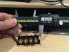
Now that the case of the power cable/socket is closed, I can more focus on the modification of the speaker binding posts. As I have shown in previous posts, I purchased some customs binding posts specifically tailored for the CA-1000 but for the reasons explained earlier, I decided against installing them. But still, I wish to have the possibility to use my cables (which happens to have bananas) or any other speaker cables in the future. So I set on the goal to find suitable bananas plugs that are both insulated AND small enough to fit the back plates that were supplied by www.speaker-terminal.com. You can see in the pictures the actual dimensions of the ones I ordered :
 

Attachments

  • IMG_4124.JPG
    IMG_4124.JPG
    63.5 KB · Views: 157
  • IMG_4125.JPG
    IMG_4125.JPG
    64.7 KB · Views: 144
  • IMG_4127.JPG
    IMG_4127.JPG
    65.4 KB · Views: 149
  • IMG_4121.JPG
    IMG_4121.JPG
    106.4 KB · Views: 157
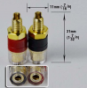
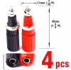
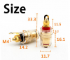
So basically, in order to fit the PCB back plate the binding post must have a diameter of 13 mm maximum otherwise they will interfere within eachothers. I have been looking very hard to find a suitable replacement but the choice of quality banana binding posts that fit the requirement is scarce. Here is a picture of the CA-1000 from Japan (on Ebay) that has something similar to what I am looking for.

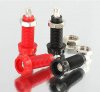
Also some other examples of binding posts I have been considering:
 

Attachments

  • s-l1600 (1).jpg
    s-l1600 (1).jpg
    94.8 KB · Views: 131
  • binding post 1.png
    binding post 1.png
    250.5 KB · Views: 117
  • binding post 2.png
    binding post 2.png
    237.6 KB · Views: 112
  • binding post 3.png
    binding post 3.png
    201.4 KB · Views: 121
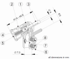
Discussing about my desired goal with Planabox, he advised against using random parts from Ebay or of similar sources as the quality often leaves to be desired and there is a lot of counterfeit products. He told me that a lot of parts manufactured in asia, those that are copper based, often have less copper to save some costs. So in the end, that would sacrifice sound quality which is not an option only to save some pennies or to fit my amplifier at all costs. He strongly suggested the Deltron 563 Series for their pure sonic performance. Cost wise, about 10$ for 4. The outside diameter is 11.7 mm so the nice thing is that it would fit. Perfect connector? Not quite so, well, not in my case actually. Not because it is not a good connector but because my Kimber KS-3033 cables have WBT-0610 Cu bananas connectors. The problem with this connector in this particular application is that there is a plastic pin that protrudes the connector so if I have the Deltron 563 binding posts installed, the WBT connectors could not be inserted. And no, I will not alter the connectors by cutting the plastic pins. But after looking at the configuration of the amplifier, he confirmed me that they could not fit since this amplifier is tightly packed and that there would be interference with other components. Case closed for this option.
 

Attachments

  • 551-0100.jpg
    551-0100.jpg
    27.5 KB · Views: 77
  • Deltron 563 Series.png
    Deltron 563 Series.png
    27.9 KB · Views: 67
  • 0610cu.jpg
    0610cu.jpg
    55.6 KB · Views: 76
  • WBT-0610Cu Drawing.png
    WBT-0610Cu Drawing.png
    271.5 KB · Views: 67
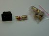
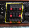
So instead of shopping on the intarwebz for binding post of unknown origins that could significantly impede sonic performance, I decided to rely on Planabox for the ones he carries (only quality parts BTW). Here is the suggested binding post. At first, it was believed that they would fit but actually after close inspection, they don't as the outer diameter is 13.7 mm. In this case, there would be interference IF using the supplied PCB back plates (which have a center to center distance of 13.0 mm). So, as stubborn as I am, I will not leave things like that. The suggested solution would be to machine a single custom back plate that would cover all the back of the actual 3 bindings spring clips. You can see the delimited area in yellow. I am confident that according to the work done on the AC/IEC plug, this would look totally professionnal. Again, I don't want this modification done if it's going to look ugly. By using a single back plate, that would extend the area a bit, actually large enough, to accomodate a secure center to center distance for the use of the banana binding posts shown. I am actually set on this one.

Edit:
One thing I forgot to mention about why the size of the diameter of the binding posts matters is that I am limited by the screws center to center distance of the original back plates. In order to use binding posts with bigger diameters, I will have no choice but to enlarge the center to center distance of the screws (which now is 60.0 mm). The backplate option would correct this altogheter.
 

Attachments

  • 100_6598.jpg
    100_6598.jpg
    39.4 KB · Views: 107
  • 1076279-yamaha-ca1000-integrated-amplifier - Copie.jpg
    1076279-yamaha-ca1000-integrated-amplifier - Copie.jpg
    53.4 KB · Views: 116
Last edited:
I have found an option that could work without any serious modifications but I have not talked about it to my tech. Deltron offers banana binding posts that would allow me to use my cables. The 552 series would be the ideal solutions IF the fit is not too tight. According to the drawing, the diameter is 12.7 mm. The theorical gap between the binding posts would only be 0.3 mm; I feel it is a bit too close even if those are insulated but I will contact my tech to see what he thinks about this option.
 

Attachments

  • Deltron 552-0100.jpg
    Deltron 552-0100.jpg
    8.9 KB · Views: 48
  • Deltron 552 Series.png
    Deltron 552 Series.png
    59.5 KB · Views: 45
Last edited:
For those curious about the modification of the AC/IEC plug and the use of an audiophile cable, I can testify that there is an audible sonic improvement. Compared to the stock cord lamp, there definately is more authority in the bass and less harshness in higher frequencies. Feels like things have been filetered from noise. Not totally sure about this one but it feels that I do not have to crank as much the volume as before to get some sound. Right now I am using a XLO Ultra 10 cable that I borrowed from my friend but last week I purchased a Shunyata Black Mamba HC/CX take care of this task. I had very good results with this specific cable in the past and I still regret that I have sold the two that I had a few years ago to upgrade to the Cobra Z-Tron...

Edit:
This Yamaha CA-1000 is really impressive. I am thrilled at how good it sounds. From a design that is more than 45 years old, that says a lot. And, I am still using a simple CCA that is connected using cheapo 3.5 mm to RCA cable with not DAC in between. Speaking of DAC, I also purchased a Bryston BDA-3 to pair with the amp. I chose this model mainly because it has 4 HDMI inputs and a HDMI video pass thru. This is very useful for me as my 2 channels setups also serves for home cinema. I will get the best of both worlds.
 
Last edited:
I went for "Binding Post 3" in post #14, yes, cheap chinese carp(?). Required minor drilling of plastic backing plate.
It is a tight fit but does the job. Used same setup in 2 other CA-1000's. Can't justify spending $50+ on binding post.
Keep in mind what the originals are
 
I went for "Binding Post 3" in post #14, yes, cheap chinese carp(?). Required minor drilling of plastic backing plate.
It is a tight fit but does the job. Used same setup in 2 other CA-1000's. Can't justify spending $50+ on binding post.
Keep in mind what the originals are

I get your point. I plan to keep this amplifer for a while and after all this I believe I would be quite reluctant to sell it at a loss. The ones shown in post #16 are made in Taiwan. Quality stuff, nothing compared to mainland China. They are 25$CA for a set of 4 which is not too bad.
 
Back
Top Bottom