• The move to the new server is done. There are some software and database maintenance updates in process. This has us passing the hat around to help out. We appreciate any donations. Seriously, even a dollar helps. The payment page may be found here - https://www.audiokarma.org/support.html

My Yamaha CA-1000 Restoration / Modifications Thread

My opinion... fusibles resistors must be checked, if they are still within spec then ok to leave them in...

The CA-1000ii is slightly better than the CA-1000, this pair has a different sound campared to the 1000iii/1010 and the 2000/2010.
These are all great integrateds, the end choice will come down to what sound you like and speaker matching, my pick is the
1000ii...maybe, the 1010 is a beast and the 2010 is refinement, again all opinion...
Thanks mbz, I've read your contributions in a few places on the 1000ii, appreciate you responding!

I'm thinking of just getting it, checking (maybe with help from the knowledgeable folks here) --- and if it needs to be replaced maybe its something I'll tackle. I know my way around a soldering iron, electronics --- but have never undertaken anything like a complete overhaul of an integrated or anything that scale.

If they did need to be replaced, how much disassembly is required in the case of the 1000ii? Is it a simple change, or does it require tearing the whole thing down?
 
  • Like
Reactions: mbz
If they did need to be replaced, how much disassembly is required in the case of the 1000ii? Is it a simple change, or does it require tearing the whole thing down?
The CA-800/1000/ii is a PITA to work on. FR's on function and tone boards can be easily tested in circuit, simply remove shields.
Replacement on function board is reasonably easy. Removal of knobs/front face is required to access tone board. The problem
is the filter board, need front end disassembly to check its FR, this job is not difficult, just a PITA.

I'd be asking the guy which/if any FR's he tested.
 
The CA-1000 I recently rebuilt had a couple fusisters that required replacement. I would expect that if the person who did the rebuild was remotely competent they checked them while they were working on the thing. If they didn't, I don't know that I'd trust the rest of the work they did. I am very much a novice when it comes to this gear, but one of the first things I learned was to check fusisters, especially when already in there.
 
Just acquired a CA-1000 following this old thread. Thank you for all the valuable info provided here. Once I square away some noise issue in one channel I’d like to do possibly the binding post mod as well as IEC connector. Also probably swap out some other potentially in need parts like caps on power supply board and possibly filter caps.
 
  • Like
Reactions: mbz
Just acquired a CA-1000 following this old thread. Thank you for all the valuable info provided here. Once I square away some noise issue in one channel I’d like to do possibly the binding post mod as well as IEC connector. Also probably swap out some other potentially in need parts like caps on power supply board and possibly filter caps.

Glad it's useful to you. That was my intention when starting this thread so that hopefully it would be useful to someone else who would go down the same path.
By the way, I recently sold this amplifier but I kept my second one which is in even better condition (mint is aptly right) and it has the same modifications as depicted in here. It will eventually retire in a second system upstairs. That's a keeper.
 
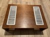
Just before I sold this amplifier, I decided to refresh the wood case as this was a long time past due step I wanted to do for myself but procrastinated along the way. I felt that would give extra value to the buyer if I was doing it.
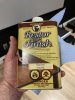
I used Howard's Retor-a-finish as shown in the picture. I selected the neutral base as I didn't want to alter the original color too much.
I followed the procedure which is rather simple. Just use #0000 steel whool and rub the wood along the grain. It's a bit unsettling as first to use steel whool but it is safe. You could use a rag but I felt the steel whool would go deeper into the grain.
Honestly, after I finished (took about 1 hour in total) I was wowed by the result. The wood looks replenished and has a nice sheen. Before I did this, the wood was faded and looked dull. The deeper grain of the wood makes the shiny grills to pop and give a nice contrast.
Suffice to say, I decided to do the same thing to my second amplifier but again, I am procrastinating huh..
 

Attachments

  • Case Work Before Refresh 1.JPG
    Case Work Before Refresh 1.JPG
    159.6 KB · Views: 41
  • Case Work Before Refresh.JPG
    Case Work Before Refresh.JPG
    180.5 KB · Views: 42
  • Case Work After Refresh.JPG
    Case Work After Refresh.JPG
    149 KB · Views: 43
  • Final Assembly Aftre Refresh.JPG
    Final Assembly Aftre Refresh.JPG
    146.3 KB · Views: 43
  • IMG_4220-1.JPG
    IMG_4220-1.JPG
    114.1 KB · Views: 43
Just acquired a CA-1000 following this old thread. Thank you for all the valuable info provided here. Once I square away some noise issue in one channel I’d like to do possibly the binding post mod as well as IEC connector. Also probably swap out some other potentially in need parts like caps on power supply board and possibly filter caps.

If you intend to do the binding posts mod using the back plate method I used, I could send you my spare one. I have had made 2 back plates for my second amplifier in case the tech had messed up (though I was totally confident he would not). Was not much more expensive to make a spare in case.
I have made this back plate even more faithful to the amplifier as shown here. I even have the AutoCAD drawing if you need it. Just PM me when you are ready.
 

Attachments

  • IMG_1124.JPG
    IMG_1124.JPG
    135.9 KB · Views: 25
  • 100_6672.jpg
    100_6672.jpg
    124.5 KB · Views: 25
  • Like
Reactions: mbz
If you intend to do the binding posts mod using the back plate method I used, I could send you my spare one. I have had made 2 back plates for my second amplifier in case the tech had messed up (though I was totally confident he would not). Was not much more expensive to make a spare in case.
I have made this back plate even more faithful to the amplifier as shown here. I even have the AutoCAD drawing if you need it. Just PM me when you are ready.
I like that back panel there for the binding posts. IM currently using little adapter. works decently but not as robust as that. Is it the whole thing or just panel minus the binding posts?
 
This is my unit. Only work done was clean all controls and Pots which was no easy task to get at, touch up some solder joints. I unsoldered and cleaned the speaker relay, adjusted the idle current and Bias.
 

Attachments

  • IMG_5518.jpg
    IMG_5518.jpg
    141 KB · Views: 24
  • IMG_5504 2.JPG
    IMG_5504 2.JPG
    111.6 KB · Views: 24
  • IMG_5503.JPG
    IMG_5503.JPG
    112.5 KB · Views: 24
Just before I sold this amplifier, I decided to refresh the wood case as this was a long time past due step I wanted to do for myself but procrastinated along the way. I felt that would give extra value to the buyer if I was doing it.
I used Howard's Retor-a-finish as shown in the picture. I selected the neutral base as I didn't want to alter the original color too much.
I followed the procedure which is rather simple. Just use #0000 steel whool and rub the wood along the grain. It's a bit unsettling as first to use steel whool but it is safe. You could use a rag but I felt the steel whool would go deeper into the grain.
Honestly, after I finished (took about 1 hour in total) I was wowed by the result. The wood looks replenished and has a nice sheen. Before I did this, the wood was faded and looked dull. The deeper grain of the wood makes the shiny grills to pop and give a nice contrast.
Suffice to say, I decided to do the same thing to my second amplifier but again, I am procrastinating huh..
I have some of this and was considering using it. The wood case is in pretty decent shape for being 48 years old! Amp is a year older than me and certainly better looking lol
 
I have a question regarding input sensitivity of the Amp being 120mv line. I’m running a Chird Mojo which at line level is 3v. I can attenuate it down to 2v even lower if needed. Is the fact the dac output is so much higher going to prove to be an issue? It sounds excellent but wondering if I should drop it to say 1v output on the Chird Mojo?
 
I have a question regarding input sensitivity of the Amp being 120mv line. I’m running a Chird Mojo which at line level is 3v. I can attenuate it down to 2v even lower if needed. Is the fact the dac output is so much higher going to prove to be an issue? It sounds excellent but wondering if I should drop it to say 1v output on the Chird Mojo?

I cannot say for sure for the mojo, but I am using a Bryston BDA-3 DAC without any issues with the RCA inputs. I know there is something written in the user manual about this and I even posted in this thread about the input voltage since I had some issues but it has been proven to me that my DAC works perfectly with the CA-1000.
Maybe @avionic could answer that question better than me.
 
I cannot say for sure for the mojo, but I am using a Bryston BDA-3 DAC without any issues with the RCA inputs. I know there is something written in the user manual about this and I even posted in this thread about the input voltage since I had some issues but it has been proven to me that my DAC works perfectly with the CA-1000.
Maybe @avionic could answer that question better than me.
The Amp doesn’t have any issues with setting voltage output to 2v. I also didn’t have issues at 3v it would just get louder faster. So in essence higher gain. 2v or I’m actually it’s 1.9v I’m planning on keeping it at unless someone has info stating it’s an issue. Now that I think about it I think the 120-150mv input sensitivity of other vintage pieces I e had over years wasn’t ever an issue either. Maybe im over thinking it.
 
  • Like
Reactions: mbz
CD Players with fixed output are typically 2V. The 120mV is the level required for the amp to achieve it's rated power(watts). The amp
will work with lower mV but it won't max out at 70W/channel.
 
So instead of shopping on the intarwebz for binding post of unknown origins that could significantly impede sonic performance, I decided to rely on Planabox for the ones he carries (only quality parts BTW). Here is the suggested binding post. At first, it was believed that they would fit but actually after close inspection, they don't as the outer diameter is 13.7 mm. In this case, there would be interference IF using the supplied PCB back plates (which have a center to center distance of 13.0 mm). So, as stubborn as I am, I will not leave things like that. The suggested solution would be to machine a single custom back plate that would cover all the back of the actual 3 bindings spring clips. You can see the delimited area in yellow. I am confident that according to the work done on the AC/IEC plug, this would look totally professionnal. Again, I don't want this modification done if it's going to look ugly. By using a single back plate, that would extend the area a bit, actually large enough, to accomodate a secure center to center distance for the use of the banana binding posts shown. I am actually set on this one.

Edit:
One thing I forgot to mention about why the size of the diameter of the binding posts matters is that I am limited by the screws center to center distance of the original back plates. In order to use binding posts with bigger diameters, I will have no choice but to enlarge the center to center distance of the screws (which now is 60.0 mm). The backplate option would correct this altogheter.
DO you remember what model and make these were? Im looking at some form Part express. IS the overall length a concern? Meaning how far in the Amp they go?
 
Dear All,
I have been working on a CA 1000. No relay clicks. Adjustment step 1: V between TP 1 & 2 unstable 5-10v. VR602 doesn’t increase more than 10V.
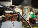
What I found is that the issue is in the L ch. If I remove 2 screws from any of the output Tr in L ch (any of of the output Tr in L ch, Tr611 or Tr612) the volatile TP1-2 can be adjusted to 15V on both Ch and both very stable. Photo attached. 1st without screws in PNP or NPN and 2nd screws in both TR.
I have swapped the whole board L to R so issues is in R ch now. I have replaced /swapped and put original Tr601-609.
I also have replaced relay and the micro switch from mouser.
Please help me if you can as I have been struggling too much.
 

Attachments

  • IMG_3439.jpeg
    IMG_3439.jpeg
    164.7 KB · Views: 4
  • IMG_3438.jpeg
    IMG_3438.jpeg
    289.6 KB · Views: 4
The screws provide power to the output transistors, removal shuts down the outputs/no bias current.
Reads like you have an excessive bias issue. Leave TP1, TP2 as is (10Vdc). With amp set to Normal operation, vol at minimum, coupler off, measure voltage between TP3 and TP4, max 47mV.

If less than 47mV then please meaure dc voltages from OUT wire on power amp board and GND.
Also measure Vdc at A,B,C,S wires to GND.
 
Dear All,
I have been working on a CA 1000. No relay clicks. Adjustment step 1: V between TP 1 & 2 unstable 5-10v. VR602 doesn’t increase more than 10V.
 
Back
Top Bottom