• The move to the new server is done. There are some software and database maintenance updates in process. This has us passing the hat around to help out. We appreciate any donations. Seriously, even a dollar helps. The payment page may be found here - https://www.audiokarma.org/support.html

NAD 1300 Recap/Restoration

thoresui

Active Member
Hi,

new project starting today. Looked for something easy to work on with good phono and some interesting features. NAD 1300 popped up in local "craigslist" and I pulled the trigger on it. Second owner described fully functional as new.

Hope for the best, prepare for the worst. I was planning to do recap anyway :).

The optics were ok, except that there were couple of surprises:

- one channel seems to be louder in normal and high output -> did not measured yet exact difference
- headphones output seems to be OK
- phono input has deep low frequency hum with or without TT is the same
- high output has also deep low frequency hum
- whole unit was "sprayed" with contact cleaner in the past, lot of oily stuff on everything
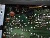
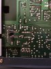
- there are some suspicious parts installed under the pcb (I know that the NAD internal quality is not the best but this really looks fishy)

Service manual exists but it is not super detailed.

Having trouble to find a picture of the pcb bottom in factory state. Would like compare with mine. If somebody owns this unit, or repaired it in the past do not hesitate to comment :).

So far I have found some mentions that all the electrolytic caps should go out.

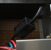
Pictures of suspicious bottom mounted parts:
IMG_4094.jpeg IMG_4090.jpeg IMG_4089.jpeg

- some choke on the mains cable
- coils and capacitors isolated with duct tape near phono outputs with rather naive soldering directly to the chassis (I have seen the cap on the other side of the board in other units, know what is its function, but having trouble to believe that they would solder it to the chassis this way)
- some resistors
 
Register to hide this ad
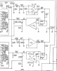
This unit has active volume, some variation of Peter Baxandall design. There is one trimpot (VR201) which is part of the related circuit, but there are no mentions about some adjustment procedure in the service manual.

Any idea what is adjusted with it and where are the measure points? Dc offset?

Screenshot 2020-10-26 at 18.31.05.png
 
Removed back panel, cleaned contact cleaner residue, resoldered RCA. Fixed and reorganised little bit the wiring of the filter nest in the phono part.

No improvement. Still hum in high output. Not confirmed yet but it looks that one channel gets weaker on the normal output after the unit warms up a little.

No audio probe or oscilloscope currently on bench, so no signal/hum tracking. Will most probably start with PSU part recap, and suspicious joints resoldering.
 
Replaced main filter caps. Which measured very good.

Continued with caps in the high output section of the board: 505,506,507,508,509,510

All of them measured bad, mostly much lower capacitance like marked on the sleeve 1/3 or less. Two of them were unmeasurable with my ESR meter.

The hum in high output seems to be less loud like before. But still not dead quiet as the normal output.

So far it looks that best tactics will be replace the e-lytics first.
 
I've got a 3300 which I believe has this preamp in it. I've had it since it was new. I had quite a few cracked solder joints that needed to be reflowed. There are pictures in a thread on it somewhere here..
I bought all the caps to rebuild the 3300, but its still in the que. I'll be following along.
:lurk:
 
It looks like HiFi Engine has the schematic and service manual as well. You can check for those suspicious parts there.
 
Already have the service manual + schematic.

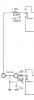
Forgot to mention the outcome of the investigation of the suspicious parts. The "quality" of installation of the additional filter was so low that it looked like some hack from som past service attempt. Which could be still true but according to the schematic the LC filter should be there:

Screenshot 2020-10-28 at 20.47.19.png
 
Btw in general soldering in this unit is not so bad as I expected. Couple of iffy joints (except the hot running pass transistors section which looked bad and two cracked joints where present), seen much worse in other vintage units. Maybe they are rotten inside :D.
 
Last edited:
PSU section fully recapped. Started with preamp section. Stopped to measure the old caps, waste of time. Most of them were out of spec or plain bad. Except rubycons, they measured fine on tester.

Replaced the relay (Omron G5V2-H1-24 fits and works well).

Initial issues still present, or maybe little bit better, most probably wishful thinking on my side. New DSO is on the way :).
 
Another recap iteration. All except phono is done. So far it looks good tested via headphone and small active speakers. Channels are balanced and hum buzz is present only with high volume setting.

Will most probably do some tests with proper power amp and with covers on after phono recap.

One side of the PSU has higher voltage. Approx 1V difference. Will try to track it down.
 
Phono recap finished. Hum went down. All caps except rubycons failed. Mostly combination of lower capacitance and high ESR (approx. 50 ohm).

---

Measured once again the differences in PSU part. Diff is approx. 1V before regulation and approx. 0.5V after regulation..
 
Similar difference is between zener diodes D602 and D603. Difference between diodes could be the reason for difference on C617, C618. Do not have 20V zener currently in stash cannot prove this hypothesis by experiment.
 
Stage one finished. Writing this after a hour of so of listening and testing.

Before recap the unit was unusable in my setup. Hum present in relatively low volume levels. One channel weaker (the level fluctuated with heating). Only usable output was headphones.

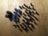
After recap the unit behaves as expected, no hum in all reasonable volume levels. Channels are balanced and thermally stable. Sound quality is much better. The sound before recap was tired and colored. Almost all Yec branded caps were failed in one or multiple ways (super high ESR, increased ESR, almost non existent capacitance, ...). Rubycons tested good. There are no real ventilation holes in the chassis which could be the reason why the caps did not aged so well.

Played only couple of minutes from one vinyl record. Sounds nice, will need to listen more.

Will do more listening and stability test before possible next stages.

IMG_4099.jpeg IMG_4098.jpeg IMG_4097.jpeg
 
Last edited:
Stage II candidates (ordered):

- finding out the purpose of the VR201 trimpot, replacing with new one and adjustment
- I have a 220V version which is currently running in 230V grid (real voltage around 236V) service manual mentions that for 120/240V usage resistors R601 and R602 should be 22ohm instead of 10ohm 1W
- power supply tweaking (lowering difference between +/- rails, better heatsinks for pass transistors, better bridge rectifier)
- more caps replacements (there are still green mylars and lot of ceramics)
- installing sockets and trying different op-amps
- replacing resistors on key positions with metal film
 
The purpose of the VR201 was the whole time in plain sight (in case I read the schematics correctly):

- it is only in one channel
- it s 1K trimpot
- it is in series with 1K8 resistor
- second channel has no trimpot, but instead it has 2K2 resistor


The sole purpose of the trimpot is to ensure that both critical resistances are equal (it adjust one channel to equal resistance value of the other) one. NADs way how to avoid matched high tolerance parts :).

I can either replace and adjust the trimpot or remove it together with 1K8 and 2K2 resistors and replace with matched 2K2 pair of 1% metal films.
 
Stage one finished. Writing this after a hour of so of listening and testing.

Before recap the unit was unusable in my setup. Hum present in relatively low volume levels. One channel weaker (the level fluctuated with heating). Only usable output was headphones.

After recap the unit behaves as expected, no hum in all reasonable volume levels. Channels are balanced and thermally stable. Sound quality is much better. The sound before recap was tired and colored. Almost all Yec branded caps were failed in one or multiple ways (super high ESR, increased ESR, almost non existent capacitance, ...). Rubycons tested good. There are no real ventilation holes in the chassis which could be the reason why the caps did not aged so well.

Played only couple of minutes from one vinyl record. Sounds nice, will need to listen more.

Will do more listening and stability test before possible next stages.

View attachment 2021727 View attachment 2021728 View attachment 2021729
Very nice writeup.

In regard to the YEC branded caps, I discovered this after I recapped my 1300:
YEC.jpg
 
Regarding the VR201. There is also R231/232 (680 ohm) in the path that also needs to be matched/paired if the trimpot would go out.
 
Yet another hypothesis is that the trimpot is needed to compensate the error on the "balance middle" position on balance pot. Need to measure it in circuit. :idea:
 
Another iteration on this preamp and plans adjustment:

- finding out the purpose of the VR201 trimpot, replacing with new one and adjustment -> this is not completely resolved, see explanations under the list
- I have a 220V version which is currently running in 230V grid (real voltage around 236V) service manual mentions that for 120/240V usage resistors R601 and R602 should be 22ohm instead of 10ohm 1W -> will pass on this one, unit works like this already couple of years
- power supply tweaking (lowering difference between +/- rails, better heatsinks for pass transistors, better bridge rectifier) -> heatsinks and bridge rectifier are good enough for now, detailed description below
- more caps replacements (there are still green mylars and lot of ceramics) -> unit sounds good, passing on this one for now
- installing sockets and trying different op-amps -> because of high supply voltage it is rather complicated to find compatible opamps, this can wait, not sure if its worth the effort and money
- replacing resistors on key positions with metal film -> passed on this one

I am still not sure what is proper test point configuration for VR201 trimpot adjustment. It si definitely there to fix some imbalance between channels related to simple resistors tolerance or main volume tracks imbalance (or even balance potentiometer part?).

When I tried to measure resistance of the whole "route" between R232 and opamp leg connected to C263 I have got proper expected reading in kOhm for one channel and unexpected reading in MOhms for other one (the one without trim pot). Which indicated that there was some capacitor in way. Did not have conditions for proper reverse engineering, it was just quick attempt to confirm my hypothesis.

---

The voltage rails difference was indeed causee be simple difference betwee 20V zeners D603 and D603, not a real issue just wanted to know if I understand it right. Replaced with more closely matched pair just for the fun.
 
Back
Top Bottom