First I'd like to say I'm very grateful to thoresui, Audiobro, NoiseyBoy and everyone who has carefully documented their experiences with the 1300 here.
I have a second-hand 1300 open on the bench right now, and need to do a second pass switch and pot cleaning, and am putting together an order for replacement electrolytics. Generally, when I opened up the unit, I was amazed at the sheer depth of paleolothic flux that encased the underside of the PCB. The second thing that troubled me was that the vicinity of the first power regulator stage (topside) was tanned a very deep brown relative to the rest of the PCB. More on that below. My unit has a problem with a *very* noisy (pink/brown, not 60Hz) right channel in phono (both MM and MC), and a very dodgy MM/MC selector, which could be related.
- some choke on the mains cable
I don't have this in my 1300. In fact, all power wiring before the transformer is soldered, to my surprise. Although I suppose that this is less of a consideration on appliances with relatively low current draw.
- coils and capacitors isolated with duct tape near phono outputs with rather naive soldering directly to the chassis
I'm missing all of this - feeling left out! No sign of corresponding improvisations topside. Everything looks relatively clean, with the exception of the cap soldered to the body of the MM/MC selector switch...
I have resistors soldered underneath JW105. These look to modify the volume control circuitry. Haven't looked too closely.
In addition, I have another couple of caps in the vicinity of the input to IC209, the last opamp before the main output stage - maybe a bit of high frequency bypass.
I'm glad to her that main filter caps still measured well, although they're the easiest thing in the entire unit to replace. I'm also very grateful to the folks that measured all the "outgoing" capacitors. I'm definitely focusing on caps other than the Rubicons.
Continued with caps in the high output section of the board: 505,506,507,508,509,510
Interesting that all the caps in the main output stage were so bad. I'm guessing that this is due to initial quality rather than to age and stress.
Regarding the Power Supply:
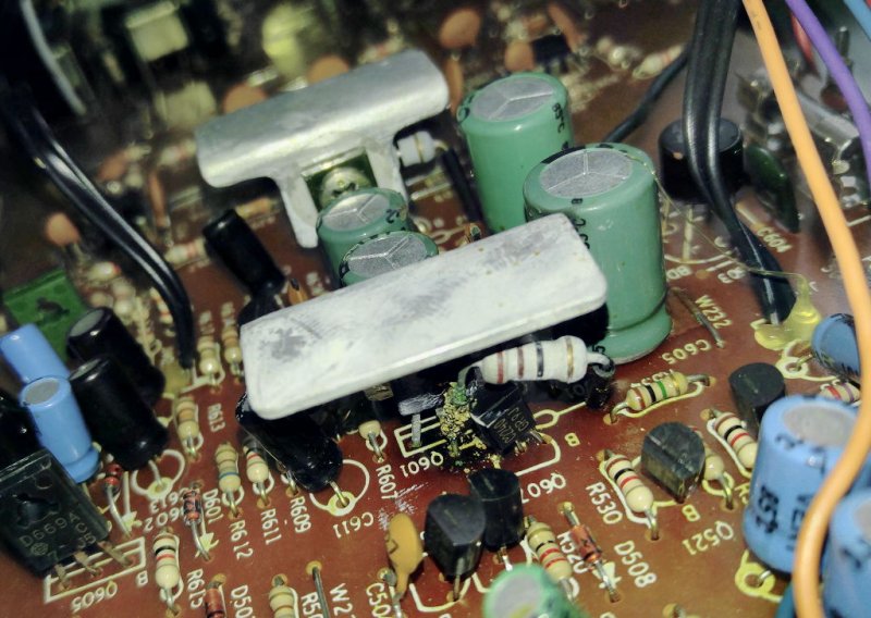
I see an almost even +/-19.2V at the output of the second stage regulators, and relatively cool Q605/Q606 pass transistors. Interesting that you have the 220V version and 10ohm R601/R602. Mine are 21ohm, and are called upon to dissipate rather too much power. In fact, R601 seems to be dissipating almost 900mW, whereas R602 is only ~300mW. The result seems to be this:
. It runs, but it doesn't smell great.
I'm glad you didn't replace yours with 22ohm!
The voltages of note in my PSU are:
- after the bridge: +34.9 / -36.1
- after Q601/Q602: +24.5 / -23.5
- after Q605/Q606: +19.3 / -19.2
I measure 4.4V across R601 (200 mA) and only 2.8V across R602 (127 mA)
I'm seriously considering replacing R601/R602 with 15ohm resistors, and seeing whether I can improve on the homemade-looking heat sinks on Q601/Q602, especially if I'm going to ask them to drop more voltage. I'm concerned, though, that the (+) rail is being asked for almost twice the current that the (-) rail is!
I have noticed that Q601 and Q602 are seriously hot.
It's likely that R601/R602 are contributing significant radiated heat! In my unit, Q601/Q602 are dissipating only ~1.25W each, and R601 especially is dissipating almost 1W. I've been thinking of not only replacing the 21ohms with 15ohms, but how to sink them or thermally couple them to modified sinks for Q601/Q602. Did you end up making any changes to these sinks?
There are no real ventilation holes in the chassis
That may be a contributor to the fact that my PSU seems to have been braised gently over the years. I was thinking of perhaps coupling the heat sinks to the top cover using (deep-ish) thermal pads. I wouldn't want any additional stress on the legs of Q601/Q602, though.
installing sockets and trying different op-amps
I came to the same conclusion about these relatively high voltage opamps. Unless I could be sure of a dramatic difference, I don't see it being worth replacing any of them.
If somebody has the time for experimenting than in theory replacing the 20V zeners in regulated PS with some lower voltage type (15-17V) could bring down the supply voltage for opamps and allow using more accessible modern opamps. Not sure what it would do with the rest of the circuit.
Clearly this would be the best way to go about replacing those opamps with more modern/hi fi ones. Keep in mind that the existing draw from Q605/Q606 is ~ 100mA (for all the opamps). If you choose to drop more voltage across them to yield lower rails, these two transistors will pay with heat. Based on other measured voltages and the opamps' draw, I'd say they're currently dissipating 400-500mW each (and have no heat sinks). Your mileage should vary linearly with voltage difference...
I do have an ngpice simulation of the NAD 1300 PSU which agrees more or less with what I measure, although I don't have models for the big transistors. I'll try lower zeners on D602/D603 and get back to you. I don't see why it shouldn't be stable. Hotter, but then newer opamps would probably draw less current.
Cheers!



 .
.