• The move to the new server is done. There are some software and database maintenance updates in process. This has us passing the hat around to help out. We appreciate any donations. Seriously, even a dollar helps. The payment page may be found here - https://www.audiokarma.org/support.html

NAD 2200PE upgrading

yes, thanks . I did watch that. I need to order some of the 2 watt resistors.
im confused about the bias. the Idle bias voltage on the service manual says 7.5 +/- 0.5 but I read here to set to 10 ? I set my 2 too 7.5 ...do I need to change that to 10?

I still havnt decided if I can do this . these amps appear to be easy to get to and work on. I may need to buy a new solder iron.

Make a free account here: https://www.hifiengine.com/ and download the service manual. The spec is 7.5mv +/- .5
Higher bias reduces crossover distortion but at the expense of more heat and shorter component life.
I run mine at spec bias and try to adjust offset as close to 0 as possible.
I used this relay: https://www.newark.com/imo-precisio...dc/relay-automotive-spdt-14vdc-45a/dp/74R1551
 
Last edited:
Make a free account here: https://www.hifiengine.com/ and download the service manual. The spec is 7.5mv +/- .5
Higher bias reduces crossover distortion but at the expense of more heat and shorter component life.
I run mine at spec bias and try to adjust offset as close to 0 as possible.
I used this relay: https://www.newark.com/imo-precisio...dc/relay-automotive-spdt-14vdc-45a/dp/74R1551


I already looked at service manual...the specs I quoted came from that. I set it like it said to 7.5 & 0 ....

I have decided not to tackle this job instead. lol....its not feasible at this time.

thanks for the replies ! !
 
the bias voltage should be 7.5mv (+/-0.5)- and a good soldering iron (and desoldering tool) is necessary as the PCB track can lift
 
I have been recapping and modding NAD 2200s for a while now- and wanted to give some details back to the AK community:

I have selected a number of mods from Pilots and others listings, and these seem to make the majority of difference:

C215-218- yes replacing the 2.2uf 50v with 470uf 50v makes quite a difference, "more bass" and better dynamics- nichicon PW
C111-114- I have not been able to find COG Ceramics to replace these- however I added 47uf 50v in parallel with each of these (across the 18v supply lines) and this again seemed to provide better dynamics - nichicon PW
I tried Pilots swapping of C109, C110 to 2.2uf 50v Wima- but ended up going back to Nichicon FG 10uf 50v- which gave more solid square wave response at frequencies below 100Hz
C107,C108- these were 820pf ceramics (circuit states 1000pf film)- so replaced these with WIMA 100pf 50v film
C203, C204- I tried a few versions (2.2uf Film, 10uf Film- both WIMA, Nichicon KL, Nichicon FG) and finally settled on ELNA SIMLIC II 10uf 50v- for me this kept the detail and was smoothest- also kept the LF square wave tidy.

I replaced the 2043DD IC's with LM49860- I had tried the OPA2134 (which is an IC I like), but again for me the LM49860 is better suited to the amp-perhaps as it is BJT as is the 2043DD
else I replaced all the other electros as follows:

Power supply- Nichicon PW same values
Power amp- all PW except c223, C224, C311, C312, C313,C314- all FG and C203,C204- ELNA Simlic II as mentioned
input amp- c109,c110 FG, C115,C116 Nichicon KA
plus the 47uf mentioned above
10000uf 80v with Nichicon or equivalent
the 10000uf 120v are unobtainable, and the 160V versions are both expensive and dont fit- so I have some 10000uf 125v sourced from China- which I plan to try, though part of me is worried they will explode- so as long as the original caps are within spec(which they are at present) I tend to leave them alone.

for me this is the best NAD mod yet- more bass, better dynamics and measures well, though there is some low frequency phase shift and roll off from about 50hz downwards-the LAB inputs less so as expected.

one thought is to bypass the 10k ufs with a film cap (1uf?)- but again I have not tried this as yet.

Thanks a lot for this list, it has been extremely helpful. I have only one question: I’m unclear about the 47/50 caps in parallel that you add to C111-114. Are they just in parallel with the ceramics? Your comment about them being across the 18v supply lines makes me doubt.

My idea is to put them in parallel with C111-114 on the solder side, but I’m a bit unclear on how to position them given that they are polarized.

and finally, what’s the rationale for adding these 47uF caps? Just curious. Thanks!
 
The 47uf caps provide additional power rail decoupling and availability to the tow IC's. Make sure the polarity is respected-pin4 is negative on the IC, so the 47uf should have -ve to that pin.
I position the 47uf by using the original holes for the ceramics and bending their leads 90 degrees so that they "hang down" from the PCB and then the ceramics are in parallel with the 47uf,
soldered onto the 47uf on the track side of the PCB. It is neat and resilient.

Thank you so much for this explanation, that makes it very clear!

Im confused about something: I was looking at the picture you have in quirksaudio about this he amp mods (https://quirkaudio.com/?p=810) and it looks like you have the positive end of C114 connected to pin 4, instead of the negative, what am I missing?
 
Hi everyone, just recapping NAD 2200, love this amp, downloaded the service manual, but my input PCB is SW 610 and not SW 594. All other details match. Does anyone have the SW 610 details? Thanks so much
 
Did you download this from HiFiengine ?
file:///C:/Users/KjellO/Downloads/hfe_nad_2200_service_en.pdf
Thanks Kjello, I just had a look on Hifiengine, but the service manual states 610 input pcb but the schematic shows C115 and C116 which my SW610 does not have, does that make any sense to you??
 
Thanks Kjello, I just had a look on Hifiengine, but the service manual states 610 input pcb but the schematic shows C115 and C116 which my SW610 does not have, does that make any sense to you??

Not really, I belive there is a difference in the powersupply UK/Euro/US spec
But was not aware of the different input boards
 
Thanks Kjello, I just had a look on Hifiengine, but the service manual states 610 input pcb but the schematic shows C115 and C116 which my SW610 does not have, does that make any sense to you??

Is there a PE and a non-PE version?
 
Is there a PE and a non-PE version?
thanks Kjello, I did not know until I started redoing the elect caps, had two leftovers, eg C115 and C116, it was only then that I noticed that the input PCB is 610 not 594. Have not been able to find the schematic/PCB layout anywhere. The unit is 2200, not a PE. Australian version.
 
there are differing versions of the input board. C116/C116 were excluded from the later 2600A/2700 input boards, which suggests your input board is one of those later ones. I cant remember seeing a 2200 with the later board.
what is the first 4 digits of your serial number?
 
there are differing versions of the input board. C116/C116 were excluded from the later 2600A/2700 input boards, which suggests your input board is one of those later ones. I cant remember seeing a 2200 with the later board.
what is the first 4 digits of your serial number?
Thanks pwauk, the serial no is A 50500117, had it from new, had a look at the service manual for the 2600/2700 and the input cct pcb is SW 692, maybe there are other service manuals out there??. Still, no sign of SW 610 schematics anywhere, strange don't you think?
 
The serial number is an early one, so you have an early version of the input board, which did not have C115/C116 installed. It would be worth looking at the 2600/2700 input boards and perhaps modifying yours to match those- excluding the additional transistors, but including the additional decoupling caps. There are a number of changes to the feedback on the IC's and some other values. Do replace the ceramics (particularly the 820pf-sometimes this is 1000pf) ceramics with WIMA FKP.
 
The serial number is an early one, so you have an early version of the input board, which did not have C115/C116 installed. It would be worth looking at the 2600/2700 input boards and perhaps modifying yours to match those- excluding the additional transistors, but including the additional decoupling caps. There are a number of changes to the feedback on the IC's and some other values. Do replace the ceramics (particularly the 820pf-sometimes this is 1000pf) ceramics with WIMA FKP.
Thanks pwauk12, I don't seem to have the mentioned ceramics on my input PCB?? wish I could find the circuit diagram for the SW 610. Looks like TA7317P is misbehaving, not dropping the RL output coils before PS discharges, so get a thump through the speakers when powering off. Don't have the equipment to test the timing/sequence of this theory, so it's a bit of a guess. May order the IC and change. Checked the relay contacts/operation and they seem fine, powering-up/protection circuit operation/sequence is fine. It's a bit hard to troubleshoot with just a DMM at hand. your advice is most welcome and interesting but please don't go into any trouble.
 
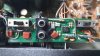
can you post a photo of the board? and are these the original relays?
Thanks for your interest pwauk12, pic attached. I just checked the volts on TA7317P and they seem a little off from pin 1 they are .3, 1, 0.7, 2.4, -.7.5, 1.14, 2.3, 1.2, 3, so I guess the IC is OK but have some other problem. 20210630_144958.jpg 20210630_145008.jpg 20210630_145029.jpg
 
Back
Top Bottom