• The move to the new server is done. There are some software and database maintenance updates in process. This has us passing the hat around to help out. We appreciate any donations. Seriously, even a dollar helps. The payment page may be found here - https://www.audiokarma.org/support.html

NAD 3020 Rebuild and Upgrade

I have two projects saved with Mouser. One is pretty much all the caps and resistors, the other is all the small signal transistors, diodes, power switch, TO3 mounting kit etc. If anyone would like me to share these projects to make it easier for them to order, please PM me your e-mail address. Once again, these are just as a starting point, you might need/want to amend what's on there. But I did just order these myself to start rebuilding an early 3020 I have, so they aren't all bad.

And the progress on this has been moving forward with all the speed of a rampaging glacier. The problem is, the 3020 I'm working on was just a pile of parts when I got it, with several key pieces missing. I managed to find some suitable angled aluminum to use as a heatsink, but needed to borrow some friends cut off saw and drill press. After a while, I bought a cheap cut off saw from China Tools AKA Harbor Fright, and cut and drilled it myself.

What other problems have I come across? The speaker jacks were missing, so I had to modify one from a 7020 receiver to fit. Then, the balance control broke off the board,so I need one of those. Plus, the headphone jack was missing, and none of my 1020 preamps use the same jack. :sigh:

Don't worry, once it gets up and running, I'll start a new thread about it.

Lee.
 
Something that should be clarified about these NAD 3020 amps is how to adjust the bias and offset. Early amps can be identified as those which have the four main smoothing caps behind the headphone jack, later ones have these in the center of the board, and even later ones have just two larger caps.

For the early versions, it says to measure across resistors R653 and R654, but these are not fitted on the board, at least not on the ones I've ever worked on. These resistors are also not shown on the schematic, not very helpful either, they are in the component listing however (confusingly as R653 and R656), listed at 0.22 ohms. Fitting these resistors is straightforward, but you'll need to cut the track underneath them as they are shorted out. If you have fitted trimmers (recommended), you can then adjust the bias to between 5 and 11mV. I adjust for 11mV, just so I can say "these amps go to 11".

For the later versions, a 1 ohm resistor is already fitted in each channel (R653 and R654 again), and there should be a solder bridge across it. Simple unsolder this, and measure across it. Again, if you have taken the step to fit trimmers, it is easy to adjust the bias current to within 30 to 60mV. Some versions of the service manual suggest somewhere in this range, others like for the 3120/3020B say to adjust it for 30mV. I try and stick to 30mV or slightly higher.

Just make sure you are using the correct resistor and set the bias for that resistor. There's no reason why you can't use a 1 ohm resistor in an early amp, set the bias to 30mV, and then bridge the resistor with solder or a wire like - VERY IMPORTANT! Rather than try and probe the boards, I always solder a couple of scraps of wire onto the pads for these resistors, and bring them out under the front panel. Just be careful not to let them touch anything, I tape them to the bottom of the panel to stop them flapping in the breeze.

As for the offset, I'm still considering this. All the 3020s I've worked on, the factory offset trimmer is always adjusted right over almost to one side. On a 20k trimmer, I'm measured resistances of as low as 4 ohms, which doesn't seem like a good use of a 20k trimmer. Even with the Bournes multi-turn trimmers, I've found I've always had to adjust them right at one end. I'm experimenting with some different values for the trimmer and the resistors around it - watch this space!

I'm adding this posting to both NAD 3020 threads I have, not to try and bump them, just in case anyone comes across one or the other when working on one of their own amps.

Hope this helps,

Lee.
 
Nice work Lee...
I dug out a 3020A that I had packed away for about 15 years. An old boss of mine used to buy up defunct recording studios and this came out of one in NYC. Since it wasn't "Pro" gear and he had no ideas what it was, he gave it to me. I decided to fire it up and it has the classic problems i.e Turn on thump (VRRRUUUMMPPP), and a major 60cycle hum in one of the channels. I have not turned it on since...

I set it aside till this winter so I could do a recap. I plan to start with caps only and see where that gets me. I have given some thought to modding the unit, but the thing is in such good physical condition, i'm thinking a simple restore might be nice.

I am trying to get everything line up and parts ordered and I have already hit my first snag. There is no shortage of service manuals for the early models like you have restored and for the 3020B and later models. But after 2 weekends of looking, I cannot find a manual for my vintage (SN: A3243376). If AK Members have one, Please let me know.

I am also very curious about your choice of capacitors. I am an Audio Engineer, but work at the system level, not component level. So while I understand what the components do and have done field repairs on PCBs, I am basically a noobe... Can you explain your choice of Low leakage Caps where you used them? While I realize there is probably more "snake oil" (marketing) than science in Nichicon's Premium Audio grade caps (KZ, FG), I am surprised that I don't see more being used in 3020 recaps that I have searched on the webs. I am sure that most new name brand electrolytic's that I choose to put in will exceed the quality of what I am replacing, I am just curious of yours and others thoughts.
 

Attachments

  • IMG_0256.jpeg
    IMG_0256.jpeg
    73.7 KB · Views: 409
  • IMG_0266.jpeg
    IMG_0266.jpeg
    110.1 KB · Views: 474
Thanks for your compliments on my work.

I think you should be able to use the manual for a later 3020, it's the same as for the 3020A, with the main power caps in the center of the board. If you PM me your email address, I can send it to you.

One thing you might want to be aware of. I'm not sure, who makes the board for your 3020A? If it says Fullet on the copper side, it was made by Fullet Electronics in Taiwan. The 3020B boards were made by another company, Dahsen, and I've found they are more prone to lifting pads than the Fullet boards.

As for my choice of caps, have a read back at the beginning of the thread. From looking at the schematics for Pioneer, Sansui and Kenwood amps, it seems they use low leakage caps in the signal path. Mark the Fixer over on the Pioneer thread has tested amps with low leakage caps in one channel, and "regular" caps in the other channel where there were originally low leakage, and has found the noise floor increases.

Hope this helps.

Lee.
 
Last edited:
I'll use "audio" caps in the signal path...I like the Nichicon ones and will look at what's in stock for the values I need. I've used KZ, KA, KT, KM, FG, Elna Silmics, etc and am happy with the sound though I haven't done any AB comparisons since I'd rather just get it all done while I'm in there. I'll typically replace the really low value electrolytics (<= 1uF) with a film cap if it will fit. UKLs for the low leakage ones (typically orange sleeved Elnas in '70s gear) and will also use them if when I replace the tantalum caps as they were also known for low leakage properties. Power supplies will. Usually get Nichicon PW, PM series or Panasonic FC, FM, FR. Bipolar caps will usually get the Nichicon UES series, though I have used Panasonic SU series and prefer film if I can get them to fit.
 
jheu02 said:
I'll typically replace the really low value electrolytics (<= 1uF) with a film cap if it will fit. UKLs for the low leakage ones (typically orange sleeved Elnas in '70s gear) and will also use them if when I replace the tantalum caps as they were also known for low leakage properties. Power supplies will. Usually get Nichicon PW, PM series or Panasonic FC, FM, FR. Bipolar caps will usually get the Nichicon UES series, though I have used Panasonic SU series and prefer film if I can get them to fit.

Light blue Sanyo electrolytics are considered by some to be evil incarnate, they are known to fail in Pioneer equipment, and there are two 0.68uF right by the bass control on the 3020. These can be replaced with film. You can also put 1uF films on the input to the power amp. You can even put 4.7uF films in the phono pre section, though the two right by the back of the case got the better of me, so I went back to a pair of Nichicon KL. Earlier models had the power supply board mounted on the back of the case, which makes things tight back there. That's one of the problems with these amps, everything is packed into that small case. I'd love to build one with four outputs per channel, but that means bigger heatsinks and a larger power transformer, which probably won't fit inside the case.

NAD3020second06.jpg


NAD3020second08.jpg


More info and pics on this thread.

Lee.
 
Last edited:
Thank you... very helpful! I'll dig a little deeper into the Low Leak audio circuit caps and see if I want to go that direction.

Leesonic> This may be a silly question, but what is the brown thermal paste you are using under the new transistors on your latest build? I was planing to replace the paste under my original transtors when I recap mine... just curious what you did because it looks so clean.
 
Earcraft said:
Leesonic> This may be a silly question, but what is the brown thermal paste you are using under the new transistors on your latest build? I was planing to replace the paste under my original transtors when I recap mine... just curious what you did because it looks so clean.

They're actual silicone thermal pads, they do the work of the mica insulator and silicone grease that was used originally. Mouser part number 739-A15036002.

Lee.
 
Darn good thread! I'm learning a lot.

Q: Why install those 'risers' for the resistors? Are they ceramic?

Your pics reflect you craftsmanship. Reminds me of those immaculate older Onkyo tube amp boards they used to make in Japan where they post them on their now defunct website.
 
Binkman said:
Q: Why install those 'risers' for the resistors? Are they ceramic?

Those were installed from the factory, I carefully made a note of where they were so I could put them back. They are used to keep hot-running resistors away from the board so they get better air flow around them. The one that drops down the voltage for the LED meter seems to be the hottest running one, at least at idle.

They can also be used to space resistors off the board that are designed to go "pop" when something goes wrong. At least the "pop" won't burn the circuit board. For example, those two resistors that are close to the heatsink between the driver transistors, they will get red hot if you have a shorted output transistor.

Binkman said:
Your pics reflect you craftsmanship. Reminds me of those immaculate older Onkyo tube amp boards they used to make in Japan where they post them on their now defunct website.

Once again, thank you for your kind comments.

Lee.
 
Hi Lee

Very pretty Job.
I have a 3020i on a shelve and you give me the desire to renew it. But I have a question: how did you clean the pcb? It looks like if it's just get out of the factory!?
And thank's a lot. It is very kind of you for sharing your experiences...

G.
 
Hi Lee

Very pretty Job.
I have a 3020i on a shelve and you give me the desire to renew it. But I have a question: how did you clean the pcb? It looks like if it's just get out of the factory!?
And thank's a lot. It is very kind of you for sharing your experiences...

G.

Thank you!

The answer to your question is - wash it! With the bare board out of the case, get yourself a cup of hot water with some dish detergent in it, and using a small brush (like an "acid brush" they sell at hardware stores), carefully clean the dirt away. Once you've got pretty much all of the dirt off, repeat the operation using just plain water to wash the soap away. Then dry it with compressed air, a hairdryer, by leaving it out in the sun, or over a heater vent. If you're like me, chances are you won't be powering it up until you've recapped it anyway, by this time it should have dried out.

Lee.
 
Light blue Sanyo electrolytics are considered by some to be evil incarnate, they are known to fail in Pioneer equipment, and there are two 0.68uF right by the bass control on the 3020. These can be replaced with film.

Lee.

I'm getting ready to press "GO" on my Mouser order so I reviewed the thread again (commitment issues). You state to use Film Caps to replace the Sanyo Devils. Would there be any benefit or dis-advantage using Solid Polymer Tantalum caps?

Thanks again for your spreadsheet, it's been very helpful. Once I'm done I'll send it to you so you have on for the 3020A.
 
Thank's a lot Lee.
Simple and efficient...
I always had dirty white things after cleaning solder flux and I asked once to a professional who told me it's necessary to blow solvent with compressed air to avoid any tracks.
Earcraft, the tantalum capacitors are bad things for me. They make short circuit when they die. If you absolutely want to use them, there is somewhere an app note telling that you must not apply more than half the nominal voltage if you want keep them alive.
 
I'm getting ready to press "GO" on my Mouser order so I reviewed the thread again (commitment issues). You state to use Film Caps to replace the Sanyo Devils. Would there be any benefit or dis-advantage using Solid Polymer Tantalum caps?

You could do, but some consider Tantalum caps to be just as bad as the blue Sanyos. If you do use these, they might go bad in another 20 years time, by which time you'll be replacing the electrolytics again anyway. There's no reason why you couldn't use Nichicon KLs here either. I just used films because they were cheap, and relatively easy to fit in place of the 0.68uF Sanyos that are part of the tone control circuit. You pays your money, you takes your choice.

Thank's a lot Lee.
Simple and efficient...
I always had dirty white things after cleaning solder flux and I asked once to a professional who told me it's necessary to blow solvent with compressed air to avoid any tracks.

Ahh... I think we might be talking crossed purposes here. The cleaning I mentioned above referred to the component side. For the track, or copper side, I just use standard flux remover which I buy from Parts Express or Mouser.

Lee.
 
I finally finished the re-cap of my 3020A. It's pretty and clean and broken :(

After firing it up and adjusting bias and DC offset, I did a listening test. The audio is was completely distorted at low level and consistent across both channels. That's when I checked the fuses to find both 4A (F3,F4) blown. After checking cap polarity and a good inspection of the traces looking for shorts, I tried another pair and they went pop the way only slow-blows can.

I guess I'm looking for some advice on where to start looking. I can say that one of the 4A fuses was blown when I started the dis-assembly so there is hope this is not the result of my handwork... but it probably is...

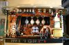
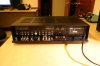
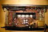
I know AK'rs love pictures so here are a couple.
 

Attachments

  • IMG_0341.jpeg
    IMG_0341.jpeg
    130.9 KB · Views: 368
  • IMG_0344.jpeg
    IMG_0344.jpeg
    126.4 KB · Views: 347
Hi,

Did you use the dim bulb tester or variac when starting her up for the first time?

Did you change any transistors or resistors or was this only a recap?

I see you took the main and bias transistors out and reapplied heat paste or maybe silicone pads? Did you check that the transistors are ok while they were out?

Did you check the new caps before installing them?

Did you make sure there is no shorts between solder pads after you soldered them? Some are so very close to each other.

Did you make sure bias and dc offset are ok before connecting speakers?

I don't know how 3020As fuses work so (2 blown but you still get audio on both channels) and have no time to search for the manual but here is what I think: If you checked that the caps are installed correctly and you are positive there are no solder shorts then I would probably start by taking out the driver, bias and output transistors and test them.

Ps. very small pics.
 
Last edited:
I finally finished the re-cap of my 3020A. It's pretty and clean and broken :(

After firing it up and adjusting bias and DC offset, I did a listening test. The audio is was completely distorted at low level and consistent across both channels. That's when I checked the fuses to find both 4A (F3,F4) blown. After checking cap polarity and a good inspection of the traces looking for shorts, I tried another pair and they went pop the way only slow-blows can.

I guess I'm looking for some advice on where to start looking. I can say that one of the 4A fuses was blown when I started the dis-assembly so there is hope this is not the result of my handwork... but it probably is...

I know AK'rs love pictures so here are a couple.
You might want to consider starting a new thread on the troubles you are having with your amp. Piggy-backing on existing threads like this one, sometimes you run the danger of nobody looking because they've seen the thread before.

The 4A fuses are for the output transistors, and the two driver transistors, so you have a problem here. Sure, there could be something bad further upstream causing the problem, but it's unlikely (but not impossible). I would start checking to see if any of the transistors are shorted to the heatsink. Then I would check to see if any of them are bad, there is a thread elsewhere on checking transistors if you need help here. Check the drivers as well, the 2N6553/6556 or whatever yours has fitted. Finally, it's not impossible for the bridge rectifier to go bad, and cause the fuses to blow. If you pull the outputs and the drivers, and the 4A fuses still blow, it's the bridge rectifier.

Lee.
 
Back
Top Bottom