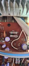
Needed R635. But since R633 gets no current only thing left is R629 and R641. For this I want the voltage at the junction with C625 to GND.R605 measures 0v


Needed R635. But since R633 gets no current only thing left is R629 and R641. For this I want the voltage at the junction with C625 to GND.R605 measures 0v

Sorry my typo- I meant R635 measured 0vR633 measures .038v and R605 measures 0v
Is that R641 directly below R629?Needed R635. But since R633 gets no current only thing left is R629 and R641. For this I want the voltage at the junction with C625 to GND.
Yes. According to the schematic you should get -26.5 V. I expect bad resistor, dry joint or PCB crack.Is that R641 directly below R629?
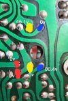
Assuming the 2 together are R641 and below it R629, I have identified the solder points on the underside of the board. In the attached photo I have marked R629 in blue, R641 in Yellow and C625 in red. Can you tell me where to place the probe to test the GND?Is that R641 directly below R629?
I'm working 7 days a week for the next month but will get into that mid November and let.you know how it went. Thanks again for your time and expertise. To see be patient while i slowly go through it is so helpful. I owe you one! I'll be in touch mid NovemberI see a green ring through the hole in the PCB and I take it that would be the 1.5k R629. There is no voltage across it so it's fine. The other one must be the 1.0k R641 and because it has the full negative rail voltage across it (it should read minus 46.1 V BTW) it will test infinity. Replace it with a fresh 1.0k/2 W resistor and that should restore nominal operation.

Ok will do thanks so much BradLooking at the solder joints on the board in post 45 I can see problematic ones.
I had LOTS of cracked solder joints on my 3300.
Spend some time just reflowing anything that even looks slightly suspect and add a bit more new solder as well. Preferably while looking at the board under magnification.
You might just find that all your issues go away.
I think there are pictures of the bad joints in my thread on the 3300…
Had to go back to 2018 to find it,but here’s some photos of very obvious bad joints. If there is even a hint of a circle in the solder ring just reflow it.Here are the solder joints. I can't believe that the amp was functioning with a board like this.
View attachment 1192927 View attachment 1192928 I must have fixed 2 dozen joints that had the appearance of a crack ring around the part lead. I suspect that as I got on a roll doing this I got sloppy and created a bridge somewhere. The amp is in protection now, and I'm on the lookout for a bridge... Hopefully whatever happened did not damage any parts, except the fuses. When I replace parts, I check each joint with a magnifying glass to be sure I'm happy with it. Once I started touching these up, and often adding a bit of fresh solder, I neglected to do that. Another lesson learned.
I suspect that as I turned the amp over some parts moved around, causing my loss of bias when I previously had it.
Yes I see what you mean.ill have a look with my head worn magnifying glassHad to go back to 2018 to find it,but here’s some photos of very obvious bad joints. If there is even a hint of a circle in the solder ring just reflow it.