• The move to the new server is done. There are some software and database maintenance updates in process. This has us passing the hat around to help out. We appreciate any donations. Seriously, even a dollar helps. The payment page may be found here - https://www.audiokarma.org/support.html

NAD 7100 Troubleshooting

Those resistors are good, I'm getting too excited to find possible broken pieces! For reference, the center lead of the transistors are the ones that are +/-, the other sides. I'm not getting the 24V on either of the emitters.
 
Before we go there, I'm getting +/- 35V around of readings in the collectors of Q501 and Q502, and ground from the emitter and bases.
Collectors of Q501 should be about +35 vdc
Base of Q501 should be +25.1 vdc
Emitter of Q501 should be +24.5 vdc

Collector of Q502 should be -35 vdc
Base of Q502 should be -25.1 vdc
Emitter of Q502 should be -24.5 vdc.

You are getting + 35vdc on all the Q501 pins and -35 vdc on all the Q502 pins?
 
Probably should read all your posts before responding :). So you have the +/-35 vdc on the collectors, but zero on the bases and emitters? If that is the case, then disabling the 18 volt regulator should not have had any effect. Curious.

If the above is really the case, please measure the voltages on the B, C, and E of Q503 and Q504.
Screenshot_1.png

Without the load of the 18 volt regulators, the +/- 24.5 volt regulators are providing only a few mA of power to the phono preamps. Would be little or no drop across R505 or R506.
 
Those voltages look like they are with C529 still shorted - please remove that short. I think I am going to need to have you remove all the transistors in that voltage regulator strip and test them with the diode range on your DMM. That would be Q501, Q502, Q503, Q504, Q505, Q506, Q507 and Q508. Be sure to keep track of which part came from where, and it's orientation.
 
Q501,502,505,506 are good at 6.5 V, but painful to get out. Checking the easier ones now
What do you mean by "good at 6.5V". If you are checking between each pair of leads (total of 6 measurements) using the diode mode of you DMM, then you should expect so see .40 to .70 for a forward biased junction and OL or other open indication for a reverse biased junction. Do need to check these out of the circuit.
 
So sorry, I guess the diode readings should be unit-less, but my DMM gives a V afterwards. I was thinking that was a goofy choice of units. I took them out, and tested them.

Q501,502,505,506 gave .65 on the two correct directions and open on the other four.

Q503,Q507,Q508 gave .7 in the two correct directions and open in the other four.

Q504 reads .7 from the base to the emitter one way, however the collector to emitter can is showing .004 either way tested, which is an internal short, no?
 
Yes, Q504 is bad. A collector-emitter short on this part will shut down both the + and - 24.5 volt regulator, as the positive side is mirroring the negative side. You will need to find a replacement for Q504.

The application here is non-critical, almost any PNP with high enough current and voltage ratings would be OK. I'd suggest a KSP2907A https://www.mouser.com/ProductDetai...=sGAEpiMZZMshyDBzk1/Wi8oN7VHZ91OkLqsDkJCp/c8=

When you get the replacement, just reinstall Q501, Q502, Q503 and Q504 first, and we can check the 24 volt regulator befor going to the 18 volt regulator.
 
Think you got the emitter and collector reversed when measuring Q501 & Q502. The pinout from the front is E - C - B.

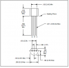
The pinout on the NTE159 is different than the 2sa1015. You'll have to bend the leads around a bit to get the right leads into the right holes. First pix of the NTE is with the flat facing you, leads down. Second pix is bottom view.
Screenshot_2.png
 
Still doesn't look right. In the current configuration, what do you see for voltages at P521 and P522 (these are wire wrap posts on the board). Should be > +/- 30 VDC.
 
Back
Top Bottom