• The move to the new server is done. There are some software and database maintenance updates in process. This has us passing the hat around to help out. We appreciate any donations. Seriously, even a dollar helps. The payment page may be found here - https://www.audiokarma.org/support.html

NAD 7175 Left Channel No Sound

Btw, would this work also to find the audio signal? I don't know how to use it though.
DSO 138 DIY Oscilloscope Kit Opening Source 2.4" TFT 1MSPS Digital Oscilloscope Kit with DIY Parts & Probe, Handheld Pocket Sized 13803K, SMD pre-soldered+case https://smile.amazon.com/dp/B0971BGDRT/ref=cm_sw_r_apan_glt_i_Z0M2XFKYFBX1JVEFW014

maybe something like,
https://www.ebay.com/itm/323226807744
You need to assemble the case, bit of a pita... and find a 9V supply or use battery.
Keep in mind, it's a toy, if you probe higher voltages it will smoke.
 
Also can you help me trace the L audio signal in the schematics. I'm getting lost in the upper right, the transistors are.
Problem could be anywhere, some basic checks. Check resistance of emitters resistors R640,1,2,3, amp powered off, measure in circuit, expect about 0.5ohms.
Measure dc voltage at TP601 to GND/chassis, repeat for TP602 to chassis then measure voltage between TP601 and TP602 ie, bias. all voltages should be in the mV range.
Check that the low voltage (non-pe) rails are ok, measure voltage to GND at D708 cathode (+ve rail) repeat for D712 anode (-ve rail)
If all ok, you could try your DMM at R6501, set to mV and increase volume as before, repeat for R6502, these R's are connected to the base of the driver transistors.

Hopefully something simple like failed diode causes power rails down.
 
mbz, just to double check. Do I check the dc voltage of TP601, TP602 and between TP601/TP602 with the amp ON? Also do I dc voltage check the D708 and D712 with amp ON?

Also when using the audio probe, do I trace it through the bottom of the circuit board? Thanks.
 
Last edited:
mbz, just to double check. Do I check the dc voltage of TP601, TP602 and between TP601/TP602 with the amp ON? Also do I dc voltage check the D708 and D712 with amp ON?
It concerns me greatly that you ask that question. Yes the amp needs to be ON. While the amp is plugged in and switched ON at wall outlet, the amp contains lethal voltages. If you are not sure what you are doing then best to leave it to someone else, not worth a 911 call...

Also when using the audio probe, do I trace it through the bottom of the circuit board?
Whatever is easiest, solder side or component side
 
mbz, thank you very much for the concern. Yes I'll be sure to property insulate when doing testing when the amp is ON.

My plan is to do component testing first with amp OFF, diode and resistance. Then do the audio probing. I'll do the voltage testing last. Thanks.
 
That amp probably has less than 120 volts being generated inside but take a look at the capacitors. What is the highest voltage capacitor in the unit? Solid state stuff runs on low voltage, high current. Tube stuff runs on high voltage, low current.

With power off, have you taken ohm measurements between the right side and the left side?

With power on, carefully take voltage readings between the right side and the left side.

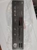
Got a pic of the front of the amp?
 
Here's a quick pick of the Left channel transistors. I noticed some brown stuff around the solders.

Cademan, I'm currently checking ohm readings bet the Left and the right. They are correlating with each other. No significant difference in readings between L and R. I have not checked the capacitors though.
 

Attachments

  • IMG_20220209_122646_1.jpg
    IMG_20220209_122646_1.jpg
    142.4 KB · Views: 5
The brown stuff is just flux. If the right and left side pretty well match with ohm readings then all the output transistors are fine and your problem lies elsewhere. Can we get a pic of the front controls? I suspect maybe the tape monitor switch/button if it has one.

EDIT: Oh, make sure the left channel jumper isn't pushed in too far. And....are you able to test the power amp at the main ins with a separate source like a phone?
 
Last edited:
Cademan, yes I'm using only the power amp section. I've used a cellphone connected directly to the Main INs. Also I've used the preamp section of my other amp, a NAD 7150. Both scenarios gives me no sound on the left channel for this NAD 7175.

I've check continuity fro Main IN port to power amp board. They are intact.

I've checked L channel wire going from power amp board to right before the relay. Continuity is intact via DMM. Signal continuity also is intact from the point where the L channel wires go out from the power amp board, back to a couple of output transistors. Confirmed with DMM continuity test. Other L transistors doesn't create a beep with the continuity test. Maybe they only engage with the Power Envelope circuit?

I guess the next thing is to do an audio probe. I just need to find at least a 100v cap.

Again, thanks for all the help.
 

Attachments

  • IMG_20220209_163634.jpg
    IMG_20220209_163634.jpg
    79.8 KB · Views: 0
The output transistors are good so its gotta be something simple preventing power from getting through. Check all those ribbon cables and check for any cold solder joints. :idea:

And yes, your best bet for a good diagnosis is a signal tracer.
 
All cables going into and out from the power amp section are intact via DMM continuity test. Can I safely do continuity tests on all power amp components (amp OFF)? I'm not gonna short anything?
 
All cables going into and out from the power amp section are intact via DMM continuity test. Can I safely do continuity tests on all power amp components (amp OFF)? I'm not gonna short anything?
No worries as long as it is turned off and unplugged.
 
Back
Top Bottom