• The move to the new server is done. There are some software and database maintenance updates in process. This has us passing the hat around to help out. We appreciate any donations. Seriously, even a dollar helps. The payment page may be found here - https://www.audiokarma.org/support.html

NAD3155 in protection mode

Timggg

Active Member
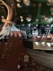
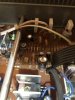
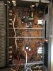
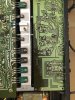
Hi All, newbie here looking for advice on troubleshooting of a non functioning NAD3155. I was about to purchase the amp but on arrival at seller’s place for a demo, he informed me it wasn’t working likely due to cracked connectors of the “bridging pins” and gave the amp to me, which I was really happy to accept. I opened up the casing, checked these connectors at home and found the connector housing (black pvc?) to have cracked - pins were loosed. I tried my best to have the pins secured, powered up the amp but noted the protection light is on. Did a quick check on the pcb and didn’t find anything that’s obviously wrong expect a cap that has partially “blown” on the top with tiny bit of brown liquid seeping out.

The seller indicated the amp was functioning but a friend must have tried to bridge the amp and somehow damaged the connectors.

Appreciate advice on what to check and troubleshoot further. I’m thinking of replacing the connectors first (could I get these ? I’m in Kangaroo land), then do some basic cleaning of the board with IPA. Not an expect on electronics but can certainly run some checks with multimeter and perform basic soldering.

I’ll try to attach some photos related to findings & descriptions provided above. The seller indicated the amp has been recapped when he bought it.
 
Register to hide this ad
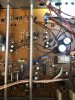
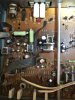
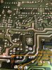
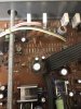
Photos added…..I hope I’m not breaching any forum rules. Please let me know if there is anything I need to correct and I’ll get them sorted. Thank you
 
C707 sure looks failed to me.
It doesn’t seem like the unit was recapped based just on that part…
Regardless you need to sort out the mess of those connectors in the back. If they short something you will just chase your tail around.
 
Yep C707 definitely needs to be replaced. This could be a main reason for the protect-mode being on....it is in the bridging circuit / pre-driver stage.
And I'd look at why C622 was replaced; currently it is an axial instead of radial form-factor (in the power-off-muting circuit).
 
Main filter caps possibly new, UCC-KMH series, also some newish panasonics(?) Certainly more work needed.
 
Thanks all. Very helpful….I’ll proceed with :
- replacing C707 (with this cap https://www.jaycar.com.au/1000uf-10...os=4&queryId=a5b0651b817fb5a7ca46b76b0508f31e)
- replace the connectors (can I get like for like replacement parts, if not, what options do I have here?). These are some connectors / mounts from a local electronic shop “jaycar” (https://www.jaycar.com.au/search?text=Rca+mount+&CSRFToken=ef20eb7a-db25-4996-bbce-20158b2b805e)

Will head to jaycar this weekend for the replacement cap to start with.

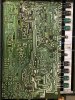
FI - I’ve checked the pcb boards (rear sides) and they all look normal to me. Attaching some photos for reference
 
Update - researched internet and found rca jacks (pcb mount) with lookalike pins that may be suitable - example given in link (https://www.ebay.com.au/itm/2x-Righ...349624.m46890.l49286&mkrid=705-154756-20017-0). Jus needing to find a suitable jacks (right dimensions) and look at how to mount/secure the jacks to the amp’s black plate. Will need to desolder existing jacks out first, replace with new, solder legs and secure jacks to black plate.

Am I on the right path ? Is there any alternative option (easier) for jack replacement ?
 
Yea, for certain the damaged rca jacks need to be replaced. Maybe see if some ebayer is parting out a NAD chassis and has similar parts.

If you don't have a schematic, hifiengine.com (free account login required) has a service manual plus a better scanned schematic available for download.

I would not discount the solder connections as being acceptable even though boards look clean. These PCBs are from the mid-80s, probably have gone through many heating / cooling cycles which will weaken solder connections over the years. You can see the PCB discoloration from the power supply components (C9xx, R9xx, D9xx, Q9xx). These components (especially the e-caps) are possibly out of spec as well. I use an eye-loupe / magnifying glass to examine the solder pads, looking for rough, non-shiny, bullseye-ring shapes and reflow the solder pads / joints (maybe even remove the old solder and replace with new).

Don't go wild either doing changes; find and replace your RCA jacks, replace the evidently blown capacitor, hookup a current limiter (DBT) to protect from shorts.
If OK no shorts but still in protection (you may need to override DBT or use a higher wattage bulb for the power supply to operate), continue your debugging.

When you change something test with DBT,....etc, continuing the debugging cycle.

Good luck, have fun.
 
Thanks jhjove for your advice - very helpful.

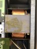
Bought a replacement cap for C707 - same V & uF - but it’s a bit thinner and slightly longer (see photo). Should not be a prob I reckon.

Will replace C707, next DIY a DBT tester while searching for similar NAD connector or equivalent.

You mentioned in an earlier post re C622 being axial vs radial form-factor…is that an issue and what check do I need to perform?

Lots of learning to come and really look forward to getting this amp back alive, to drive a pair of vintage Gale 401c. They are said to be very power hungry to go down to 2-3 ohms. I’m using Onkyo TX NR905 currently and am pretty happy with it but someone advised they need big amp to really shine. As an alternative to those big & $$$ amps, a few vintage amps which were said to be capable of driving 401s better (at a fraction of price to give over 90% performance of those big $$$ amps). These include NAD3020, Rotel RX840bx, pioneer A-400. I saw this NAD3155 and thought I’ll give it a try.
 
Bought a replacement cap for C707 - same V & uF - but it’s a bit thinner and slightly longer (see photo). Should not be a prob I reckon.

Will replace C707, next DIY a DBT tester while searching for similar NAD connector or equivalent.
I didn't mention before, I would go to the next available working voltage for the e-cap, ex: instead of 10V, go to 16V.
Always stay same capacitance value but it is ok to up the working voltage value. But use what you purchased.

You mentioned in an earlier post re C622 being axial vs radial form-factor…is that an issue and what check do I need to perform?
Not an issue, just a sloppy installation. Other than this, I just pointed it out because it was an obvious area that was serviced prior to you opening up the amplifier.

Just take your time, be methodical and test after changes.

FWIW: I have a 3155 that I got from ebay as "parts-only, DOA". When I opened it up it looked like it was growing a beard on the chassis. I did not even attempt to power it on.
I disassembled the chassis, separating the heatsink (so it could be washed). On the PCBs I used IPA and foam-swabs to clean. Many solder joints were cracked, I probably went over >75% if not more of the solder joints. In the power supply area (the 9xx component area) a resistor had broken loose as an example of extreme solder joint failure.
Also replaced all the e-caps. Many were visibly overheated from the label shrinking down exposing more of the aluminum top. Additionally these were from a crappy manufacture (Marcon), fortunately none failed (exploded) but many tested more like a resistor than a capacitor.
End result is this amp is wonderful sounding and plays much louder than the 55W/channel spec.
 
Thanks jhjove - very clear. And what a major restoration you’ve done there on your 3155 !

Visually, the pcb on my unit looks not bad so I’m hoping it’s an easy fix (= within my tiny capabilities).

Ps- I think I can exchange the 10v capacitor to higher 16 or 25V cap. Will give jaycar a call tomorrow.
 
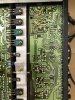
C707 removed - see photo showing solders on 707 and others nearby.

Some brownish spots can be seen on some points (2nd photo) - are these left over flux from soldering ? My plan is to just clean the board with IPA, probably brushing with soft toothbrush,
 
Yes, flux+rosin. IPA and a foam swab or soft brush will help clean that residue.

Some solder pads should probably get some attention:
ak.3155.edit.jpg

Just two that I picked out, there look like others as well.
 
I wanted to point out (in the image I edited) that the solder joint on the bottom is the "bullseye" look I would reflow for certain.
 
Thanks jhjove. Just read your reply and the guidance to identify problematic solder joints on the board to reflow.

FI - I’ve replaced C707 with a 16V cap, checked connections at RCA jacks with pins installed, and powered up the amp. Protection mode was still on . Didn’t use DBT as I haven’t made one yet.

Unfortunately not an easy fix and have started to check on the internet on means to check/test the various components.

Next steps :
- clean pcb
- visual check for damaged components & cold joints with magnifying glass (your edited photos really help me here) & reflow suspicious joints
- power up amp and if not successful, continue lots of reading/research re electronic checks (venturing into new territory - a bit daunting)
- consider replacing e-caps

Wrt rca jacks - I’ll be also looking at jumpering internally if I can’t find similar jacks.
 
Back
Top Bottom