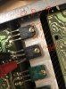
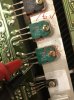
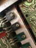
Q704 is a 2SC2690 NPN, pinout is E-C-B.
Your "continuity" test is reporting a short from the Collector to the Base. Were the results the same when you reverse the leads?
The collector of these types of transistors (TO-126) are connected to the mounting plate...and so when attached to a heatsink (without an insulator) the heatsink is connected to the collector.
Q901 is a 2SD414 (NPN - ECB) showing the collector+heatsink connection. OK
Q904 is a 2SB548 (PNP - ECB) the collector should be connected to the backplane...to the heatsink via the screw, I'd check this again.
IC902 is a 78M24 (24V regulator - VIN-G-VOUT)
pin1 is Vin, pin2 Ground and pin3 is Vout....I think the heat-sink tab is isolated from the external connections.
So far any power-on you've done hasn't smoked anything and just puts the amp into protection, correct?
This area we are discussing is providing the power for the amp.
It is worthwhile to check the values of the +/- 46V supply and the +/- 24V supply. These are DC values in reference to chassis ground.
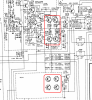
See schematic below:
RED arrows for the +/-46V
Light BLUE arrows for the +/-24V
On the DMM VDC setting, connect the black probe (COM) to the chassis metal, probe
carefully with the red probe to the ARROWS indicated.
If you want to be
Extra careful use spring-loaded test leads to hook on the component leads then power-on the amp. Get the reading, power-off, move the lead to the next component then power-on....
If you only have pin-type probes just use care to not let the probe slip.
Example for measuring the voltages:
- RED probe to emitter on Q901 should read out an approximate +46V DC value.
- RED probe to emitter on Q902 should read out an approximate -46V DC value
- RED probe to pin3 on IC902 should read out an approximate +24V DC value
- RED probe to emitter Q904 should read out an approximate -24V DC value.





 soon.
soon. . I guess I need to prioritise this as it has been mentioned and queried several times by several members…


 )
)

