• The move to the new server is done. There are some software and database maintenance updates in process. This has us passing the hat around to help out. We appreciate any donations. Seriously, even a dollar helps. The payment page may be found here - https://www.audiokarma.org/support.html

NAD3155 in protection mode

Happy New Year…

I’m back !

Still waiting for my mini-grab probes to arrive so decided to progress further :
- Q704 cleaned up and resoldered
- unsoldered the new capacitor C704 and checked voltage readings with DMM. Readings suggested healthy (check was done to confirm I haven’t damaged it due to overheating when soldering it last time). But I also bought a pre-owed DMM with capacitance readings - used that to check but reading is zero. Max range on the meter is 200 uF far below the 1000 uF for C704. Same zero uF reading on the old blown capacitor. I’m not sure if it’s faulty or I should expect a max range reading of 200 uF from that meter? But I soldered it back anyhow
- checked supply voltage on 2 points with good readings (+47V on Q901 & -24V on Q904). I initially measured very low V readings and thought I’ve confirmed power supply issue but happy to realise pretty soon it was because I didn’t switch on the amp yet :naughty:

Will check on Q902 & IC902 when mini grab probes arrived.

Are there any suggestions on what to do in the meantime ? I’m thinking of getting another new cap for C704 - is this necessary ?

Note I’ve contacted the previous owner of the amp who confirmed it was functioning well before and only went into protect mode after it was returned with damaged pre-out main-in rca jacks by the buyer before I got hold of the amp.
 
build a DBT.
+1

Incircuit testing can be tricky, you need to look for alternate paths where the MM current might flow.
Previously mentioned c-b short on Q704 however tested ok out of circuit. problem might be with Q703 and a c-e short?
upload_2022-1-7_6-58-57.png

Still getting a Q704c-b short?
 
Thanks rickl & mbz. Yeah - DBT is next . Almost forgot about this…

Received my mini grab probes today so completed the remaining power supply measurements (all good giving - 48V at Q902 and +24V at IC902).

Slightly higher with +47V & - 48V at Q901 & Q902 (vs +/- 46 V) - assumed no prob here.

Measured continuity of the resoldered Q704 in circuit with same previous results - continuity ok at points marked in attached photo (including c-b continuity good).

Tested Q703 in circuit with results below:
- c-b positive continuity with 73 ohms
- diode PNP test (B-E 0.113V, B-C 0.017V for both +ve & -ve probes on B). It should give OL when +be probe is on B). Thus suggest faulty Q703.

I think next step is to desolder Q703 and test off circuit. If faulty, get a replacement. Think I’m on the right track (?)

DBT build tomorrow hopefully.

Enjoying the learning journey and thanks for the advice from all…really appreciate all responses thus far :thumbsup: (or would have already given up)
 
has D703 been examined?
If Q704 shows a C-B short in-circuit but tests ok removed from circuit then suspect D703 for a short.
 
Progressing slowly :
- DBT built
- powered up amp with DBT (20W bulb) : bright so short somewhere
- checked D703 in circuit (open circuit in both directions suggesting opened diode)

I’ll do the following next:
- unsolder Q703 & D703 off circuit. Will report results

Any suggested test or sequence of tests with DBT are most welcome.

Attached photos of DBT for reference.
 
Last edited:
20Watt bulb is too small. I think it better to use 60W to 100W bulb for better indication.

On a different tangent, I reviewed through this thread, due to the physical damage on the rca jacks can you check and see if the speaker jacks are shorted?
Power off, unplugged, just check continuity from red to black for each channel on A and B selections.
Just a sanity check.
 
Tested with 100W bulb no light at all.

And 60W bulb - lit up then dimmed - see photo.

Q703 removed and tested to be faulty (mbz is correct :thumbsup:) :

Black probe to B:
E-B : 0.108V
C-B : 0.124V

Red probe to B:
E-B : 0.112 V (should be OL)
C-B : 0.128 V (should be OL)

D703 removed, diode test showed 0.516V, OL opposite direction. This suggests it is good.

So D703 is good, Q703 is faulty. (Q704 tested good off circuit).
 
Last edited:
Measured continuity of speakers jacks - results for points with continuity are shown in photos.

No continuity between any red & black terminals.

All normal I think (?)
 
Planning to solder D703 back.

And what should I do next ?
Nice job.
  1. replace the failed Q703
  2. power up with the DBT
  3. if bulb lights then dims as before then remove the DBT and plug direct to mains (The DBT may interfere with the relay engaging and leave in protect because of the drop in line voltage.)
Hopefully the amp is no longer in protect then.
 
Thanks jhjove…not possible without the help from you, mbz and others.

Just checked for 2SA970 (Q703) - it’s obsolete :(

Searched further and found suggested replacement KSA992FBU.

Will check locally but are the 970/992 from eBay (China) good ? Wanting to avoid waiting to only receive resistors that are not good.

Prefer to source locally but these are not available at local jaycar stores. Will search locally further.

Hopefully a new Q703 will fix the fault …
 
So the part is 2SA970 not 2SA991 (as in schematic)?
My first choice would not be ebay, only last resort.

And yes, KSA992 is probably a good choice.
 
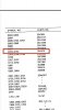
I saw 2SA970 from part list in the service manual and yes, just realised it’s 2SA991 in the schematic.

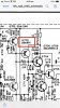
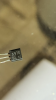
Just checked the resistor and it showed A970 on the body, so, schematic is not up to date I think.

Will try to source locally.
 
Back
Top Bottom