• The move to the new server is done. There are some software and database maintenance updates in process. This has us passing the hat around to help out. We appreciate any donations. Seriously, even a dollar helps. The payment page may be found here - https://www.audiokarma.org/support.html

NAD3155 in protection mode

Update:

Unsoldered the suspected resistors :
- R802, 815 and 816 tested off circuit with resistance per specs. They are not faulty
- R718 measured OL, therefore confirmed faulty

I then resoldered the old R802, 815 & 816 back and redid resistance measurement in circuit. I have exactly the same readings/pattern of readings per before :
- R802 readings oscillating between OL, 47 kΩ, OL, 47 kΩ…..
- slow to steady readings on both R815 & 816

I then unsoldered R802 and soldered in the new jcar resistor and remeasured resistance - same oscillating readings between OL & 47 kΩ. Similar to the old R802. This confirms R802 is good. Somehow something is causing the oscillating readings while in circuit.

Holding here for now awaiting for a new R718 which definitely requires replacement and suitability of the altronics resistor. New R802, old R815 & R815 are in circuit.
 
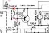
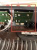
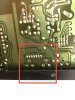
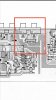
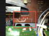
Wrt oscillating OL-47 kΩ readings on R802, would it be useful to check the few adjacent components ie C801 & Q801 (see photos). Some adjacent resistors have been checked to be good previously
 

Attachments

  • AB464788-0228-4D53-A61D-555B086000F0.jpeg
    AB464788-0228-4D53-A61D-555B086000F0.jpeg
    128.4 KB · Views: 5
Is this a fusible resistor
Increasingly difficult to find true fusible resistors. Most opt for metal film types of the correct power rating, flame proof/retardent is desireable, resistor should be mounter off/above the board for better air circulation. The linked resistor looks good.
 
- R802 readings oscillating between OL, 47 kΩ, OL, 47 kΩ…..
Incircuit measurement can be a little tricky, you want to measure R802 resistance ie,

upload_2022-1-28_7-15-10.png
But those points are also for measuring C801 and also for Q801b-e.
Your multimeter current will be charging up C801 until OL is reached, values will ramp up.
R802 tests OK out of circuit, safe to assume it's ok.
 
Increasingly difficult to find true fusible resistors. Most opt for metal film types of the correct power rating, flame proof/retardent is desireable, resistor should be mounter off/above the board for better air circulation. The linked resistor looks good
Thanks @mbz.

I will get the R718 replacement from altronics for the time being.

Am comparing measured resistance of the 180 odds resistors from values in the schematic. Already saw a few with much bigger differences. Will finish check, then remeasure the resistance in circuit and off circuit as required. Will replace those with values outside initial tolerances shown in schematic (mostly +/- 5%).

B847C028-D8EB-4300-A6CB-77835FA67A1A.jpeg
 
Incircuit measurement can be a little tricky, you want to measure R802 resistance ie,

View attachment 2465810
But those points are also for measuring C801 and also for Q801b-e.
Your multimeter current will be charging up C801 until OL is reached, values will ramp up.
R802 tests OK out of circuit, safe to assume it's ok.
Very helpful explanation re OL & C801… for me. Thanks
 
Update:

Soldered in new R718 (from altronics)…amp was in protect mode when powering on, then relay clicked, and went off protection mode. The fault is hopefully rectified :rflmao:
7BFA957F-38C9-479D-9218-33DD9D87D650.jpeg

But yet to be tested as I still need to replace the rca jacks that have broken into pieces. Planning to just simply connect/solder in wcables on the pcb iso using jacks (will lose the pre-out/main-in functions but that’s ok for now). Will review schematics to ensure I connect the cables to the right points, then test the amp with speakers connected.

F91E25FF-A86F-4D80-B5E9-9C3CF710D52D.jpeg
 
Thanks @jhjove … definitely not possible with the guidance of @mbz & also yourself.

Tried to review schematic on how to solder in jumper cables for the pre-out main-in bridge…reviewed some other threads too but I’m not confident at all (even with only 6 holes on the pcb). So was hoping to get some guidance on this.

Photos show pcb front rear on pre-amp, main out, schematic and the cables I intended to use.

Would be great if an expect could help to provide mark up on where the cables need to be connected to/soldered on the pcb :)..

Also, is the cable (it’s a phone cable) suitable for this purpose ? See photo showing specs. Thanks
 
Jumper cables soldered in, hooked up a CD player and speakers.

No sound initially and I was worried. Turned out I was selecting CD/Aux on the “Record” selector, not on “Listen”. Corrected and it is singing … what a relief - I am so joyful :rflmao::rflmao::rflmao::rflmao:

Sharing this joy with @mbz @jhjove and all who contributed to this thread (@Bradbrews @rickl @RVT1K @dimanag) for me to get this outcome. Even a simple single post or query helped….esp when I was kind of “lost” most times. Learned a little bit on electronics from this journey - stressful but also joyful.
 
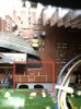
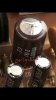
I’m back with a query on capacitor C707 that I replaced. I noted today that the new cap has shown sign of “bulging” on the top surface. Wasn’t sure when this occurred but it seems to be easing toward the same failure as the old one. See photos.

@mbz - is this likely a “car-place” issue (cap sourced from them) or are there more checks worth carrying out ?

90F8EE77-2D30-4579-86C8-59EF5FB72EF9.jpeg 19854837-D483-4FD2-A420-CC70CCE07F7E.png 6CED2907-589E-466D-82AB-283277555801.jpeg
 
Last edited:
A little early to call. Some things worth note, try to avoid using 6.6V, 10V and often 16V caps. They are generally lower spec/performance. You can always use a higher voltage rated cap (dielectric breakdown). In this case I'd go with a 16V or 25V
cap depending on available space.

Cap may be exposed to higher voltages during power up/mute period so over time... something is going on that caused the original cap to age.

C707 is part of the feedback circuit, so important for sound quality. Suggest using a quality cap.
 
Thanks @mbz…it’s currently a 16V cap. I will monitor and look to getting a better quality 25V cap next. Cheers
 
Back
Top Bottom