• The move to the new server is done. There are some software and database maintenance updates in process. This has us passing the hat around to help out. We appreciate any donations. Seriously, even a dollar helps. The payment page may be found here - https://www.audiokarma.org/support.html

NAD3155 in protection mode

Mbz…you’re really an expect. Spot on…with your skill of troubleshooting & logical steps. I’m just happy to simply follow instructions for the time being…(& to review back later to try understand your explanations etc)

Updates on resistors’ ohms:

R726 6.1 ohms
R727 6 ohms
R724 5.9 ohms
R725 6 ohms

Note for some of the readings above, I needed to press the meter probes with a bit of force to the resistors’ pins/legs or it’d give me OL readings (is this due to some corrosion/oxidation on the pins/legs due to age or an indication of issue?)

R717 leg Vdc : -47.7V

Will get a new C713 next and replace and report back. You’re a legend:thumbsup::thumbsup:
 
I'm not a big fan of that car place, wouldn't buy silicon, caps,,, there. OK for HW, LEDs and spray lube (that don't work).
RS components is a PITA forcing people into multiple buys, ie, can only buy 5+ when you only need 1. Now they've added postal charges. Where possible shop at Mouser or Digikey. Mouser has free shipping for orders over AUD60- with 3 day delivery to metro melb. Go with the jcar cap to determine if it's the source of the problem however I'm sceptical since you have the same problem on both channels... same cap failed on both channels, what are the odds... Next step, when the cap doesn't work, would be to lift one leg of R813 and R815. This will disable the protect circuit so relay will click (Do NOT connect any speakers, they will explode) then measure Vdc between emitter resistors of both channels.

EDIT: Some resistor legs have a clear/slightly amber coating which acts as an insulator, can give confusing results, those resistors look good. You should diode test the b-e junction of Q710 and 711, in circuit is ok, don't expect OL in the foward direction (red probe on emitter)
 
Noted re “car place”. Have ordered one to pick up tomorrow for troubleshoot, then Mouser later once amp is back functional.

b-e on Q710/711 diode test tomorrow.
 
Update:

Q710 & Q711 b-c diode in circuit test done : 4.26 M ohm (on both)

New C713 soldered in, powered up and in protect mode immediately:

Lifted one leg on each of R813, R815, powered up, relay clicked and measured VdC :

Left channel emitter resistor : - 45.5V
Right channel emitter resistor : -0.009V

Note : :(I think I most likely have left Q701 out of circuit after testing (1.12pm Wednesday update) and didn’t solder it back in until today. This means all readings taken on resistors ohms (7.13pm update) were done without Q701 in circuit. I clearly soldered in both C713 and Q701 before taking the readings above today. Does this impact the previous readings and diagnostic and do I need to retake any readings ?
 
Last edited:
I think the only reading that may be impacted by potentially leaving Q701 off circuit during past measurement is Vdc at R717 leg.

So I resoldered the leg of R813 & R815 back, and re-measured Vdc at R717 leg. Reading is -42.2 V (vs previous of -47.7V) - not too far off.

Guess more measurements and testing of components would follow next ….

ps - starting to review past measurements, steps of checks, reasoning against schematic and getting a little bit more understanding of the schematic etc.

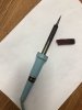
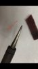
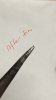
Question - sometimes while soldering, the solder seems to splash off a bit while heating up esp when directly on the iron tip & during soldering. Is there any particular reason for this and how to avoid ? Not very nice to have tiny droplets of solder splashing on the pcb… I’ve just polished the ironing tip with steel wool and tinned the tip. Photos show before & after. It’s an old used Weller W60D soldering iron that I bought recently….not sure if older than @jhjove 25W Weller :rolleyes:
 
Last edited:
You should diode test the b-e junction of Q710 and 711, in circuit is ok, don't expect OL in the foward direction (red probe on emitter)

Q710 & Q711 b-c diode in circuit test done : 4.26 M ohm (on both)
You should be using the diode function/symbol on your MM, it uses higher test currents than the resistance measurements, results are in mV. I was more interested in the b-e junction as above however 4.26Mohms for b-c (in both directions?) would indicate something is wrong. Retest Q710, Q711, all 6 combinations, in circuit.

Left channel emitter resistor : - 45.5V
Right channel emitter resistor : -0.009V
Problem is with left channel, right channel is ok

Note : :(I think I most likely have left Q701 out of circuit after testing (1.12pm Wednesday update) and didn’t solder it back in until today.
Thanks for mentioning that, don't see any harm

Guess more measurements and testing of components would follow next ….
Yeah, the general technique is to move in the direction of increasing voltage (from -45.5 to -46 then ... then to rails voltage)
Start with diode test of Q710, Q711, looking for a short rather than an OL.
 
ps - starting to review past measurements, steps of checks, reasoning against schematic and getting a little bit more understanding of the schematic etc.

Nice. :thumbsup:

Question - sometimes while soldering, the solder seems to splash off a bit while heating up esp when directly on the iron tip & during soldering. Is there any particular reason for this and how to avoid ? Not very nice to have tiny droplets of solder splashing on the pcb… I’ve just polished the ironing tip with steel wool and tinned the tip. Photos show before & after. It’s an old used Weller W60D soldering iron that I bought recently….not sure if older than @jhjove 25W Weller :rolleyes:

Ha!:rflmao:
I've wanted to buy a "fancy" adjustable temp iron, but for some reason have acquired several of these pencil types (Weller and radio-shack) from family and friends. Even have 2 of the dual wattage 100W/140W gun types from Weller...which I use for some big metal situations. But still I use the original Weller from the 80s.

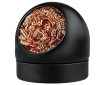
For the longest time I had used a damp sponge to clean/wipe the soldering tip, dip the tip in solder paste (for electronic use), wipe again and would get good results. But now I use one of copper metal "sponges" in a container like this:solder.iron.tip.cleaner.png
Still use a solder paste to dip the tip and clean, but no damp sponge and tips last soooo much longer.

As for the splashing of solder; maybe this is the rosin core (or flux) splashing???

After I'm done my PCB work I'll cleanup the extra rosin with a wooden toothpick to loosen the dried rosin. Then I'll go over with IPA on a foam cleaning swab wiping up the excess.
 
You should be using the diode function/symbol on your MM, it uses higher test currents than the resistance measurements, results are in mV. I was more interested in the b-e junction as above however 4.26Mohms for b-c (in both directions?) would indicate something is wrong. Retest Q710, Q711, all 6 combinations, in circuit.
Update :

Q710/711 - silly mistake again as I was measuring resistance iso diode test, and the 4.24 M ohm readings are actually on b-e of both resistors. (typo b-c in my update).

Re-diode tested in circuit (amp not powered up) with results below:

1.Q710 (PNP):

Black meter probe on b :
b-c : 0.407 V
b-e : 0.446 V

c-e : 1.109 V & readings gradually increasing (black on c)

Red meter probe on b:
b-c : 0.626 V
b-e : 0.427 V

c-e : 0.697 V & increasing (red on c)

2.Q711 (PNP)
Black meter probe on b :
b-c : 0.4076V
b-e : 0.446 V

c-e : 1.109 V & readings gradually increasing (black to c, red to e)

Red meter probe on b:
b-c : 0.832V
b-e : 1.332 V

c-e : 0.709 V & increasing (red to c, black to b)

I can’t interpret the readings (against the diode test diagram):(
 
For the longest time I had used a damp sponge to clean/wipe the soldering tip, dip the tip in solder paste (for electronic use), wipe again and would get good results. But now I use one of copper metal "sponges" in a container like this:
Was using damp sponge…now I remembered I have purchased a solder paste. Shall use the paste…and get a metal sponge (will one like for cleaning the dishes/pots fit for purpose SS vs copper ?)4FCBF0B1-B9FD-433A-9D25-CB79F9607D9D.jpeg
 
As for the splashing of solder; maybe this is the rosin core (or flux) splashing???

After I'm done my PCB work I'll cleanup the extra rosin with a wooden toothpick to loosen the dried rosin.
Aahh…must be the resin core splashing….understood. Have scrapped off the bits with a tiny screw driver and IPA cleaned, but toothpick is more gentle. Toothpick it’ll be in future.
 
2 steps forward, 1 back...
"Try hunting down the source of the high negative voltage"
By that I mean, you have -46Vdc between the emitters. Take further
measurements and move in the direction of increasing negative voltage,
eventually you will end up at the power rail. Possibly something has shorted
and is flooding the amp with -ve volts.

Connect/clip red meter probe to emitter resistors, jumper marked in pink
EDIT: Correction, connect black MM probe to jumper.
then probe each of the points below with the black probe, need to watch
MM sign carefully, MM need to display negative. You will need to follow
the schematic to work out what part to test next, start with Q710e and Q711e
then probably base for these transistors


Q707 (in red)
e R727
c c719
b c717

Q710 (in blue)
Q711 (in green)

You should get something like,
Q711e -0.01,,,-0.1
Q711b -0.6
Q707e -0.7
Q707b -1.3

upload_2022-1-23_14-42-5.png


Ensure the bridging switch at the back is turned off.
 
Last edited:
Still reads like a c-e short of Q710 or Q711, some other things you can try.
- disconnect regulated supply by lifing one leg of R905, R906, power up on dbt and check voltage between emitter resistors (pink jumper) should be close to zero, a large -ve voltage points to unregulated supply TR707, 710, 711.
- remove TR710 and 711 and connect a diode (1N4148 or similiar) between b-e solder pads, the diode banded end connects to the transistor base solder pad. DBT power up and again check dc voltage at pink jumper.
upload_2022-1-23_18-44-18.png
 
Still reads like a c-e short of Q710 or Q711, some other things you can try.
- disconnect regulated supply by lifing one leg of R905, R906, power up on dbt and check voltage between emitter resistors (pink jumper) should be close to zero, a large -ve voltage points to unregulated supply TR707, 710, 711.

One leg each on R905 & R906 lifted up, DBT powered up, Vdc at emitter resistors pink jumper measured to be - 0.1V (not large).

Note - on powering up, DBT lit & fully dimmed immediately (60W). If I powered off amp and immediately powered amp back up, no light on DBT at all. Waited a bit longer to power up, lit and dimmed immediately.

One leg each on R905 & 906 is still lifted. Do I need to proceed with the next step “remove TR710 and 711…) ?

If not necessary, I’ll solder R905 & 906 leg back and proceed with the measurements suggested in post below.
 
Last edited:
EDIT: Correction, connect black MM probe to jumper.
then probe each of the points below with the black probe, need to watch
MM sign carefully, MM need to display negative. You will need to follow
the schematic to work out what part to test next, start with Q710e and Q711e
then probably base for these transistors
 
One leg each on R905 & R906 lifted up, DBT powered up, Vdc at emitter resistors pink jumper measured to be - 0.1V (not large).
I was thinking that Q710 or Q711 were breaking down under the higher rails voltage (higher than your mm anyway). Lifting R905,6
disconnects the +/-46 regulated supply leaving only the unregulated supply, a risky assumption is that it's the regulated supplied components that's causing the problem. Reinstall R905,6. No need for diode replacement of Q710,711, need to look at the front end of the power amp.
 
Measure dc voltage at R720 and jumper marked, black probe to chassis, all parts reinstalled. testing the VR/trimmer is ok
upload_2022-1-24_7-25-22.png
 
Thanks mbz…

Measure dc voltage at R720 and jumper marked, black probe to chassis, all parts reinstalled. testing the VR/trimmer is ok
R905/6 reinstalled and readings taken :

R720 : -38.57 V
Jumper near Q705 : 0.002V (see note below)

I initially measured -38.5V on the jumper, then remeasured and the readings were staying low at around 0, -0.03, 0.01V. Last readings I took was after switching off and on the amp, touched probe on jumper -38, released probe and touched jumper again close to 0V, then readings were all over the place (most negatives). Tried powering amp off again, red probe to jumper, powered on and it gave me -38V, moved red probe and touched the other side of the jumper 0.002V, moved back -38V). Unsure why the inconsistencies…no difference between touching the probe hard or soft against the jumper (not due to contact issue).
 
Back
Top Bottom