• The move to the new server is done. There are some software and database maintenance updates in process. This has us passing the hat around to help out. We appreciate any donations. Seriously, even a dollar helps. The payment page may be found here - https://www.audiokarma.org/support.html

NAD3155 in protection mode

Inspect for dry solder joints (google for pix) in this area Q707, Q705, R721. NAD typically used an open trimmer, these were cr@p however does not explain the -38V on the jumper, expect -1.3V or so. Also, it was -46V between output emitters, so we need to look elsewhere, try R715 then jumper as marked, wanting to see over -46Vdc
upload_2022-1-24_20-40-30.png
 
Proceeded to more checks on resistors R719/720/721:

Measured resistance :
R720 : 326.5 ohm (off circuit)
R719 : 1.28 k ohm (off circuit)
R721 : 158/200/64 (in circuit) - see photos

R719/720 close to spec - good
R721 variable spec 300 - looks good (?)
 
Inspect for dry solder joints (google for pix) in this area Q707, Q705, R721. NAD typically used an open trimmer, these were cr@p however does not explain the -38V on the jumper, expect -1.3V or so. Also, it was -46V between output emitters, so we need to look elsewhere, try R715 then jumper as marked, wanting to see over -46Vdc
View attachment 2462473[/QUOTE
Just saw this - will move on to this check now
 
Measurements done (values are not over -46V) :

R715 : -15.51V
Jumper : -14.72 V (but readings jumping around like that of jumper near Q705 earlier - at times close to 0.001V). Is this an indication of cold joints?

Have “reflow” a few solder joints, will continue on this.
 
Last edited:
Inspect for dry solder joints (google for pix) in this area Q707, Q705, R721.
Conservatively “Reflow” joints on Q707, C717, R721, Q705 and the jumper. Measured VdC and getting more steady readings of -38V on the jumper (still low readings at times). Suspected may be due to “coating/seal” on jumper, moved to measure Vdc on the 2 solder joints of jumper at the rear of PCB. Vdc is steady at around -38V at the 2 joints. I take this as confirming no issue on solder joints and no abnormality here.
 
Jumper : -14.72 V (but readings jumping around like that of jumper near Q705 earlier - at times close to 0.001V). Is this an indication of cold joints?
Similar to above, measured Vdc on the 2 solder joints at the back of pcb. Vdc is steady at 15 V on both joints. So looking good. Didn’t reflow any solder joints for components along this track.
 
Completed in circuit resistors check (about 80 resistors - almost all the R7xx & R8xx resistors on the rear half of the main/control amp & power supply pcb). Yet to compare measured resistance with spec but would like to point out a few odd ones with erratic readings, readings taking too long to stabilise or bigger difference when measured with meter probes in opposite direction:

R802 - readings switching between OL & 49 k Ω (same pattern of readings with probes in opposite direction)

R815 - 34.6 k Ω & jumping up to 130 k Ω & reducing values. Very inconsistent / erratic readings

R816 - 86.5 k Ω & 38 k Ω with probes in opposite direction. Readings erratic up & down

R812 - 33.09 k Ω & 32.72 k Ω with probes in opposite direction

In general, resistance readings for R805, 806, 808, 809, 814 took a bit of time to stabilise but didn’t really fully stop after say 5 mins (but almost stabilising). Readings pretty close with probes in different directions.

R718 - 27.7 M Ω but 11.63 M Ω with probes in opposite direction

R756 - 22.1 k Ω and 21.5k Ω with probes in opposite direction (reading is pretty close)

The other readings are steady and close with probes in different directionz

The following resistors appear to be faulty requiring replacement :

R802
R815
R816
R718

Am I making the right move with the above ?

Will proceed to check other resistors R6xx, R9xxx next.
 
  • Like
Reactions: mbz
2 steps forward, 1 back...
"Try hunting down the source of the high negative voltage"
By that I mean, you have -46Vdc between the emitters. Take further
measurements and move in the direction of increasing negative voltage,
eventually you will end up at the power rail. Possibly something has shorted
and is flooding the amp with -ve volts.

Connect/clip red meter probe to emitter resistors, jumper marked in pink
EDIT: Correction, connect black MM probe to jumper.
then probe each of the points below with the black probe, need to watch
MM sign carefully, MM need to display negative. You will need to follow
the schematic to work out what part to test next, start with Q710e and Q711e
then probably base for these transistors


Q707 (in red)
e R727
c c719
b c717

Q710 (in blue)
Q711 (in green)

You should get something like,
Q711e -0.01,,,-0.1
Q711b -0.6
Q707e -0.7
Q707b -1.3

View attachment 2461286


Ensure the bridging switch at the back is turned off.

@mbz I haven’t taken readings requested in this post - is this still needed?
 
he following resistors appear to be faulty requiring replacement :

R802
R815
R816
R718
Replace these for a start. Resistors marked as FR are fusible type, replace with metal film with flame retardent coating, mount 5-10mm off the board for air circulation. All fusibles should be checked, check R712 and R801. Can use ordinary metal film as a temp measure, use same power rating (don't increase, same as increase glass fuse from 0.25W to 0.5W)
 
R712 & R801 were checked as part of the 80 resistors yesterday:

R712 : 322 Ω
R801 : 32.9 Ω

Both are to spec and good :)

Will compare readings of those 80 with specs, & check the R6xx R9xx resistors.

Will source replacement resistors for the 4 listed above in the meantime
 
Further update :

Other fusible resistors readings checked vs spec and are all good :

R762: 323.5 Ω
R768 : 100.3 Ω
R905: 10 Ω
R906: 10 Ω
R909 : 0.493 kΩ

With this, concluding all fusible resistors (all shown on the part list in the service manual) were tested.
 
  • Like
Reactions: mbz
Completed checks on the remaining R6xx & R9xx resistors (approx another 80) on the front half of the main/control am & power supply pcb. No abnormalities in readings - all look ok. Some readings are a little bit slow to stabilise as before.

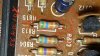
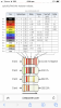
Yet to check readings against specs (of the total 80 + 80 resistors measured yesterday & today). Checked service manual and realised not all resistors are listed, needing to check values based on color. Colours on resistors are not very clear. Photo shows a few resistors, where the color of stripe for tolerance is not very clear (grey or silver ?). I assumed it’s silver 10% tolerance - not sure if correct(?).

Sourcing replacement resistors…
 
Which resistors need replacing, only R718(100/0.25W FR)? Jcar had nothing suitable. I can post you some FRN25's or
upload_2022-1-26_13-46-43.png
if you get stuck then pm your postal details
 
Thanks @mbz for the offer:thumbsup:. Let me try to source R718 locally first and if I’m stuck, will drop you a message.

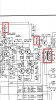
Resistors to replace are R718, R802, R815/816 (in photo).

I should be able to get R802/815/816 from Jcar (see photos) but they are 0.5W. There is no metal film 0.25W units but are available on carbon film. Do I get the 0.5W or 0.25W units and how do I know this spec (i can’t find details in part list nor schematic)?

Note - found resistors values in the schematic (no need to guess colours on the resistors now) :)

EDIT - actually Jcar doesn’t have 6.8k & 56k 0.25 W carbon film resistors too. Will explore local options
 
Last edited:
R802 (6.8k) R815 (56k) R816 (56k) can all be 0.5W metal film.

R718(FR) 100ohms 0.25W, designed to fuse at 50mA. By going to a 0.5W item
changes the fuse current to 70mA, so it is a bit like replacing a 1A fuse
with a 2A fuse... Common for FR's to drift/fail due to ware and tear over
the years ie, no downstream fault so using a 0.5W for test purposes is probably
ok. However, if there is a downstream problem then the extra mA could do further
damage meaning more work. I'll have a look at RS

EDIT RS has
https://au.rs-online.com/web/p/through-hole-resistors/8499029
which is a bit of overkill (TCR...) but has flame retardent coating. 89cents but $13- postage.
RS has lost my buisness...
 
Last edited:
Collected the few resistors from jcar.

No joy with the fusible resistor R718 yet. Contacted a few technicians - they either don’t have or not selling to public. No reply from some - not unexpectedly.

@mbz Asked altronics on availability of the resistor from RS above or an equivalent unit. They recommended this resistor https://www.altronics.com.au/p/r7534-100r-0.25w-metal-film-resistor-pk-10/#pkg. Is this a fusible resistor ? I can’t tell despite trying to search for info on the website. If good, I’ll order in. Is atronics good place to get spares vs Jcar ?
 
Back
Top Bottom