• The move to the new server is done. There are some software and database maintenance updates in process. This has us passing the hat around to help out. We appreciate any donations. Seriously, even a dollar helps. The payment page may be found here - https://www.audiokarma.org/support.html

Nakamichi 580 no audio at RCAs & headphone jack

gnexus

Active Member
I also have a 580 in addition to my dead Nakamichi 480: https://audiokarma.org/forums/threads/nakamichi-480-no-power-lamps-has-correct-volts.1110484/

This deck was also in non-climate storage for 20 years. So it also badly needed a new idler tire and also cleaning and lubrication of the transport - especially the pinch roller mechanism. That has the transport working again very nicely indeed! :)

But, unfortunately, the insulated non-climate shipping container where the deck was stored also had a small leak in the top, and the deck was directly below the top. Fortunately the deck didn't get wet. But the main PCB had lots of corrosion caused by the wet cardboard box. The bad corrosion actually got under the solder and destroyed some PCB traces! I didn't initially know about the internal issues. So I first plugged the deck in and tried to use it. That may have shorted some components due to all the corrosion. But there are no visible signs of shorts or bad components.

The bad PCB traces had to be repaired with fine wire bridges. The components all seem ok physically with no corrosion or bulging caps. The control PCB was clean and had no issues. All the controls work well.

The deck has no audio from either the RCA jacks or the headphone jack. In addition the VU meters don't move. The tape head is rising fully to touch the tape.

I could probably figure out what's wrong if I had an occiilloscope. But I don't. I really don't even know where to start with just a multimeter.

So far the only test done for the audio issue is to disconnect the record switch cable and spray some contact cleaner in the switch and actuate it. That didn't help. The switch shows no signs of corrosion.

I hoping someone here can give me some ideas on what to check without a scope. Or is a scope absolutely necessary to figure this out?

Thanks very much in advance for any replies
 
Last edited:
Register to hide this ad
Ok. I've been doing a little troubleshooting with just a DMM. Turns out you can actually do quite a bit!

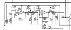
But I'm getting some very screwy readings at IC303. That chip is same 4558D op amp as in the 480. I'm getting -12VDC at pin 8! That's supposed to be +VCC. It should be POSITIVE!

R302, C309 and R311 are also NEGATIVE 12V! R148 farther away is positive. IC301 (4558D) pin 8 +VCC is also positive. Further down the circuit it goes directly to +12V p/s input. IC303 is isolated by the 1K resistor. But otherwise seems connected to +12V. So how can IC303 be negative at pin8? Wouldn't there would be a big short then?

This doesn't make any sense to me!
 

Attachments

  • Screenshot_20260805-132655464 (1).jpg
    Screenshot_20260805-132655464 (1).jpg
    64.2 KB · Views: 5
Last edited:
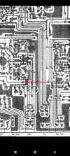
So far the readings other than at IC303(8), and R302, C309 and R311, seem to correspond with what's shown in the wiring diagram.

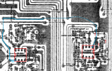
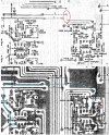
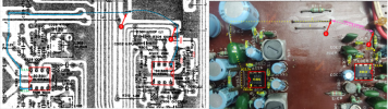
The other odd discrepancy is that this is the earlier model 580, but the PCB seems to be slightly different than what's shown in the manual, but also not the later one. There's no black wire jumper between R311 and the PCB trace to C315 which is shown in the PCB trace image in the manual for the earlier S/N's. Instead there's a standard bare wire jumper on the pad to the left of R202 which goes to the PCB trace connecting to Q303 and L301. That trace doesn't exist in the later PCB.

If that jumper was there it might cause a short because R311 is -12VDC and C315 is +12V! Still wondering how it's not shorted somewhere else...
 
Last edited:
I'm getting -12VDC at pin 8! That's supposed to be +VCC. It should be POSITIVE!

R302, C309 and R311 are also NEGATIVE 12V!
What did you use as a ground reference when you made these measurements?
I traced the two voltage lines on the schematic and they go to the right pins from the board connector pins 2 & 3.

1786056716656.png
Check the +/-12V on the input connector.
1786059369077.png
I followed the trace from IC301 pin 8 to IC303 pin 8.
Something is not right? You measured +12V at IC301 pin 8, but -12V on R302 and C309?
  1. First, check to make sure that you have 3 jumpers in place in the path from pin 8 to pin 8 (dotted lines) and that they are connecting the right traces.
  2. Since the voltage polarity changes from + to - at R311, check for bad solder or cracked traces in that area and double check you readings.
  3. Also, note that IC301 and IC303 are installed in opposite orientations as noted by the notch in the IC. Make sure you were on the correct pin when you measured the voltages on pin 8.
1786064167664.png
There's no black wire jumper between R311 and the PCB trace to C315 which is shown in the PCB trace image in the manual for the earlier S/N's.
I think the jumper was replaced with a board trace, but my copy of the board layout is bad and I can't see it well.
1786063030517.png
 
Last edited:
What did you use as a ground reference when you made these measurements?
I traced the two voltage lines on the schematic and they go to the right pins from the board connector pins 2 & 3.

View attachment 3813961
Check the +/-12V on the input connector.
That's also what I traced to yesterday. So I checked the pins and got:
pin 1 (GND) 0V, pin 2 (-12V) and pin 3 (+12V).
 
I followed the trace from IC301 pin 8 to IC303 pin 8.
Something is not right? You measured +12V at IC301 pin 8, but -12V on R302 and C309?
  1. First, check to make sure that you have 3 jumpers in place in the path from pin 8 to pin 8 (dotted lines) and that they are connecting the right traces.
  2. Since the voltage polarity changes from + to - at R311, check for bad solder or cracked traces in that area and double check you readings.
View attachment 3813992

I think the jumper was replaced with a board trace, but my copy of the board layout is bad and I can't see it well.
View attachment 3814008
You're correct about that. Something is definitely not right! Don't get it...

This board is slightly different that any board shown in the manual, as I noted in post #3 :

There is no insulated jumper wire (the curved one) on this board. It definitely looks like there never has been. There is also no board trace where you have it circled. That's for the later board, if a trace is there. This board is the earlier board in most all respects.

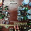
But this board, as noted in post #3, has a standard straight bare wire jumper, not shown in the manual, mounted on the board on the pad to the left of R202 and which goes to the PCB trace connecting to Q303 and L301. That trace doesn't exist in the later PCB. Maybe it's a later revision, or maybe they just accidentally left that jumper out of the manual.

I haven't yet compared the main PCB photo/parts list image to the wiring diagram. I'm currently mainly using my phone for reference so I must scroll through the manual. It's quite difficult doing things that way! So I definitely need to print out the wiring diagram and PCB layout...

The voltage readings I got were very odd! So checked and re-checked multiple times. Same readings.
 

Attachments

  • Screenshot_20260806-201013408 (1).jpg
    Screenshot_20260806-201013408 (1).jpg
    152.8 KB · Views: 1
If you assumed they were the same orientation, then you may have measured the wrong leads.
 
Here's a photo of the jumper not shown in the manual
 

Attachments

  • IMG_20260807_145407948-1.jpg
    IMG_20260807_145407948-1.jpg
    188 KB · Views: 4
Now starting the troubleshooting again from the top.
Literally! All readings are taken on component side.
No comments. Just the actual readings:

Power input pins (wire wrapped)
Pin 1: 0V
Pin 2: -12V
Pin3: +12V

IC303:
Pin 1: -10.97
Pin 2: 0V
Pin 3: 0V
Pin 4: -12V
Pin 5: 0V
Pin 6: 0V
Pin 7: -10.8
Pin 8: -11.43

IC301:
Pin 1: 0V
Pin 2: 0V
Pin 3: 0V
Pin 4: -11.77V
Pin 5: 0V
Pin 6: 0V
Pin 7: 0V
Pin 8: +11.48

Jumpers:
Long one closer to PCB front edge (not shown in manual) -11.44V
Medium length: 0V drop at center, +12V either side on trace side
Short: -12V

R148
Left side in photo above: +11.97
RH: +9.64

Others:
R311: -11.44
R301 0V
R302 0V
R303 -10.81
R323 +11.49
R225 0V
VR301 -10.75

Q303 (long jumper goes to Q303(c) eventually)
(b) +12V
(e) +12V
(c) -12V

R317 68 ohm 2W: -12V
 
Last edited:
R317 is two big 2W resistors tied together. It's at -12V and that -12V goes through that long jumper and eventually back to IC303(8).

The wiring diagram shows it to be POSITIVE!
 
Think I found it! C311 appears to be shorted!

Or, to be more precise, there's a solder bridge across the C311 terminals from my previous repairs of corroded PCB traces.

And C311 is actually totally MISSING!
LOL!!!

Looks like I need a 4.7uF 25V electrolytic cap before doing anything else...

Wondering now if the shorted C311 terminals did any other damage...
 
Last edited:
Here are the two points on either side of the jumper that is not on your board.
Can you measure the voltage at point 1 and point 2 with respect to ground.
I think this should correspond to the -11.4v and +11.97v you provided before.
If this is what it is, then we need to investigate why.

1786123775112.png
1786123858619.png
 
Here are the two points on either side of the jumper that is not on your board.
Can you measure the voltage at point 1 and point 2 with respect to ground.
I think this should correspond to the -11.4v and +11.97v you provided before.
If this is what it is, then we need to investigate why.
Please note again that the curved jumper, which would be an insulated black jumper wire, does not exist and has never been present.

#1: R311 is -11.4V.
#2: R323 is +11.97, other side +11.49

EDIT: Never mind what's below. C311 is present.

That's with the solder bridge removed and C311 missing. Have ordered a new cap. Have no clue where old one went...

Only readings that changed after removal of the solder bridge were:
Shortest jumper: -12V (previously 0V)
R323 is now +11.97V
 
Last edited:
Ok. I screwed up! Must be getting dingy again... :(

C311 is actually there. It was the "bias cut jumper" that was missing. So a solder bridge would have actually been the same thing.

I just put a jumper back in. Looks cleaner now.
 
Last edited:
If this is what it is, then we need to investigate why
That's pretty obvious. There's no curved jumper. The long jumper, that's used instead, that's shown in posts #8 and #11, is at -12V.

That's why I'm now tracing from it. It goes to Q303(c). That should be +12V. But it's -12V.

I suppose I could temporarily remove the long jumper and add the curved jumper to see if that corrects the voltage at IC303. But the other issue around the bias circuit would still be present...
 
Last edited:
Back
Top Bottom