• The move to the new server is done. There are some software and database maintenance updates in process. This has us passing the hat around to help out. We appreciate any donations. Seriously, even a dollar helps. The payment page may be found here - https://www.audiokarma.org/support.html

Nakamichi 580 no audio at RCAs & headphone jack

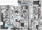
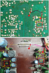
I found a photo on the internet for someone selling that board. He shows the front and back of the board.
https://www.ebay.com/itm/125186818042 (no affiliation with seller)
I cropped the back side of the board and lined it up with your front side photo.
There is the black wire jumper. I assume that because it is a "wire", on the board layout it is shown with arrow tips on each end (as opposed to a dotted straight line).
Do you (or did you) have this black wire on yours when it worked?
1786131095288.png
1786131173885.png
 
There is the black wire jumper. I assume that because it is a "wire", on the board layout it is shown with arrow tips on each end (as opposed to a dotted straight line).
Do you (or did you) have this black wire on yours when it worked?
No. As stated previously. It also definitely appears to never have been present with undisturbed factory solder. Instead there's the other jumper.

I disconnected one side of the other jumper as an experiment, and added the other one shown in your photo. Now the voltages are correct:

IC303:
Pin 1: +9.4
Pin 2: +9.5
Pin 3: +8.7
Pin 4: -10V
Pin 5: -5.45
Pin 6: 0V
Pin 7: +9.4
Pin 8: +10.1

IC301:
Pin 1: 0V
Pin 2: 0V
Pin 3: 0V
Pin 4: -11.77V
Pin 5: 0V
Pin 6: 0V
Pin 7: 0V
Pin 8: +11.48

R148
Left side in photo above: +11.97
RH: +9.64

Others:
R311: +11.97
R301 0V
R302 +4.79
R303 +9.49
R323 +11.49
R225 0V
VR301 -10.75

BUT NONE OF THAT MATTERS! Because all IC303 is for, according to the manual, is the tone generator...

Still no sound. So need to figure out why the voltages in the bias section are the opposite of what they should be. Hopefully that may lead to why no audio. Either way that issue obviously must be corrected. Then can return jumpers back to original and the voltages should hopefully be correct.
 
Last edited:
Now that IC303 is happy I'm moving forward onward from (currently disconnected) long jumper :

BIAS CIRCUIT components:
(Q303 collector goes to long jumper that goes to IC303(8), which should be at +12V)

Q303(b): +12V
Q303(e): +12V
Q303(c): -12V

L301: -12V
R317: -12V

C311(+): -12V (NOTE: C311 is not shorted)
C311(-):-11.79V

R313, 314: -12.3V
R319: +12V

Q301(b): -11.79V
Q301(e): -12.3V
Q301(c): -11.79V

Q302(b): -11.79V
Q302(e): -12.3V
Q302(c): -11.79V
 
Last edited:
I still can't figure out why the long jumper (not shown in manual) which goes to IC303(8) (instead of wire jumper in manual) is at -12V...

The jumper goes to the Q303 collector and L301. That's part of the bias circuit (see attached). Last night I was thinking that maybe C311 was shorted because it goes directly to the -12V P/S. But it's ok.

Why would the Q303 collector be at -12V? What else could cause that?
 

Attachments

  • Screenshot_20260808-135019888 (1).jpg
    Screenshot_20260808-135019888 (1).jpg
    87.6 KB · Views: 3
Since I can't figure out what's up with the bias circuit I moved on to checking the headphone amp circuit. All the voltages there correspond nearly identically with the voltages in the manual. So I assume that circuit is okay.

Therefore I would assume the issue is somewhere in the playback circuit. Is that a valid assumption?
 
I took voltage readings on playback circuit. The readings there also seem to correspond with the manual.

Then took ohm readings from playback head through record/play switch. Those readings also seem normal. So I'm running out of things to check...

The other side of IC303 is used for playback. Maybe it's not working? No way to check with DMM...

dankik:
Do you think IC303 could have been damaged by the inverted voltage at pin8? Would it make sense to replace it? I have TONS of leftover RC4558's.
EDIT:
To answer my own question: Looking at the RC4558 circuit diagram that's a definite YES!

Also:
C311, Q301, Q302 seem to check out ok in circuit. But one of them must be shorted to have -12V.

Would it make sense to pull C311, Q301, Q302 to try to find reason for -12V at L301?

Thanks in advance :)
 

Attachments

  • Screenshot_20260808-211712067 (1).jpg
    Screenshot_20260808-211712067 (1).jpg
    77.2 KB · Views: 2
Last edited:
Would it make sense to pull C311, Q301, Q302 to try to find reason for -12V at L301?
What I would do is to follow the -12V from IC303 back to the 12V trace to see which component is causing it to be -12V.
Take a good photo of the back side of the board. Hold the camera so it takes a flat photo of the trace side and component side of your board so I can compare it with what is in the SM.

Also, what is the Main PCB part number? It will be in the corner of the board similar to the photo below.
1786278416986.png
 
Last edited:
What I would do is to follow the -12V from IC303 back to the 12V trace to see which component is causing it to be -12V.
Take a good photo of the back side of the board. Hold the camera so it takes a flat photo of the trace side and component side of your board so I can compare it with what is in the SM.

Also, what is the Main PCB part number? It will be in the corner of the board similar to the photo below.
View attachment 3815437
Thanks very much for your input! :)

The board is B-7794A (big A right next to the 4).

That tracing is exactly what I did. That indicated one or more bad of the above components. But was impossible for me to test them properly in the circuit.

So I pulled them all one by one this morning and tested them. Each removed component dropped the voltage at the long jumper by around 1/3. Now they are all removed. Currently the voltage is 0 at the long jumper.

It seems each component is defective according to my very limited test equipment and diagnostic abilities:

C311 shows 7.4 uF instead of 4.7 uF
Q301 tests bad using DMM tests.
Q302 tests bad using DMM tests.

The C311 anomaly shouldn't make much difference. But it's already out. So may as well replace it. Will get them all ordered today.

Also:
Replaced IC303 just to make certain it is good.
It was okay... no changes in voltages or operation.

Thanks again! :)
 
On rudimentary testers, high leakage in a cap is often noted as a higher measured value, since the tester is likely using charge time to determine value, and leakage increases that. So, good to replace it!
 
It'll take a couple of days for the new components to arrive. In the meantime, while I know the new cap & transistors should help the bias section, and should hopefully allow the board jumpers to be put back to original, I very seriously doubt it's going to affect the audio output...

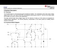
So I've been studying the schematic further. I thought the Dolby in/out button would completely bypass the Dolby ICs (IC101-201). But it appears that's not the case. It looks like playback always goes to IC101/201(9).

EDIT:
Looks definitely like the signal always goes through IC101/201. It also seems that uA7300s are not just Dolby NR. They also have op amps. Also, it seems Nakamichi uses factory matched pairs of uA7300s. So they should be replaced in pairs and tested for matched output.

But it also seems that uA7300s can be upgraded to newer A7300PC chips. Those ICs don't need to be matched and have better specs and availability, and a lower price! That seems like a good upgrade regardless of whether or not they work! But, at this point I couldn't care less if the audio sounds like a cat screeching! I just want sound! ANYTHING is better than current situation!

dankik:
Can a regular DMM measure an audio signal at IC101/201(9) to at least see if the audio signal makes it that far? Or must you need a VTVM (or equivalent) or a scope?
 
Last edited:
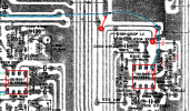
Using the board layout in the SM, I traced the +12v to the input on the connector. This is the signal that goes to the trace that you measured as -11.4v.
It goes through transistor Q303 which is turned on by the REC* signal on the base of Q303.
Follow the voltage from board Pin 2 through Q303 to R311 and IC303 Pin 8.
The path is shown in turquoise blue on the board layout below.

What make and model DMM do you have. Some have the capability to measure lower frequency sine wave signals.?
Do you have a way to generate a sine wave input to plug into the Tape In RCAs of the deck?

1786327575428.png
 
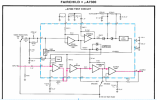
Looking at the Dolby chip circuit, it looks like for the input to get to the output the signal has to go through some amp stages before it gets there, even if Dolby is off.
Follow the pink line.
1786329035730.png
It looks like you can check the input and output of each amplifier stage internal to the chip.
1786329326043.png
 
Using the board layout in the SM, I traced the +12v to the input on the connector. This is the signal that goes to the trace that you measured as -11.4v.
It goes through transistor Q303 which is turned on by the REC* signal on the base of Q303.
Follow the voltage from board Pin 2 through Q303 to R311 and IC303 Pin 8.
The path is shown in turquoise blue on the board layout below.
Thanks for that. But hopefully I'm already past that point now. Also, post #23 already noted that Q303(b) and (c) are at +12V.
 
What make and model DMM do you have. Some have the capability to measure lower frequency sine wave signals.?
Do you have a way to generate a sine wave input to plug into the Tape In RCAs of the deck?
It's a cheap Harbor Freight DMM. But better than expected because it can check capacitance. So maybe it can measure a sine wave.

I have a Yamaha tuner that puts out a 333Hz record calibration signal. I used to use that to set the Nakamichi record levels. Suppose I could check the tuner output and see if it reads on the DMM. If the meter reads it then I guess it would be sufficient for an input signal.

Also have a test tone tape recorded from LP on same deck with discrete tones, and also sweeps from 20-20kHz. But currently don't know if the tape itself is even okay. Then would also need another working deck to cue it to the constant 400Hz tone...
 
Last edited:
It's a cheap Harbor Freight DMM. But better than expected because it can check capacitance. So maybe it can measure a sine wave.

I have a Yamaha tuner that puts out a 333Hz record calibration signal. I used to use that to set the Nakamichi record levels. Suppose I could check the tuner output and see if it reads on the DMM. If the meter reads it then I guess it would be sufficient for an input signal.

Also have a test tone tape recorded from LP on same deck with discrete tones, and also sweeps from 20-20kHz. But currently don't know if the tape itself is even okay. Then would also need another working deck to cue it to the constant 400Hz tone...
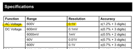
By definition, the AC range on a DMM measures sine waves (that's what AC power from the utility is, after all . . .all).. The question is other than 60Hz (or 50Hz), what is the frequency range it will read? (Noting the pic, looks like 40 to 400 . . . . So, no 1K test tones, but def enough range to be useful.)

Having said that, if you test at or close to those frequencies, it should allow you to test for signal.
 
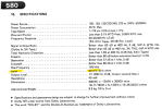
If it's this one, then ACV up to 400Hz.
Thanks. That's it! :)
I looked at the package & manual last night and didn't see any Hz specs. Hopefully then can get a reading from the tuner ouput. If that works I'm good to go! :)

You would think I'd have more test equipment. But normally have only worked on computers & printers up to now. Unfortunately I now have all these nice audio components that are all now messed up from long term storage... The Naks are just the start :(

BTW, I understand there's quite a few programs now that can take input from a sound card and emulate a scope. Has anyone used those? If so which prog is best and what's required to get input to sound card?
 
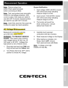
Here is the only problem with using this DMM.
The ACV resolution is 0.1V =100mV which will not detect an input voltage of 50mV (only 1/2 the minimum AC voltage).
Cen-tech CM300:
1786387416125.png
1786387594233.png
 
Here is the only problem with using this DMM.
The ACV resolution is 0.1V =100mV which will not detect an input voltage of 50mV (only 1/2 the minimum AC voltage).
Cen-tech CM300:
I now see the info in the manual. Thanks.

I'm getting 0.2VAC from the tuner. So hopefully it's at least sufficient for my purpose just to see if there's any signal getting to IC101/201(9). We'll see...
 
Good news : I'm getting 0.2VAC on the DMM from the 333Hz tuner test tone output on right channel! It's also there with music. But goes away when muted. :)

Bad news: there's only a tone on the right output, and the tone is not perfectly steady. Instead it's a bit choppy. So my tuner also has issues. :(

At least the tuner has audio output on both channels. But it seems the left side output is significantly lower. Didn't notice that previously... Also the tuner sensitivity is MUCH lower than before it went into storage...
 
Back
Top Bottom