You are using an out of date browser. It may not display this or other websites correctly.
You should upgrade or use an alternative browser.
You should upgrade or use an alternative browser.
Nakamichi 580 no audio at RCAs & headphone jack
- Thread starter gnexus
- Start date
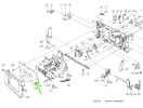
Yes. The cover plate is perfectly flat and screwed in fully.Take a picture of the cassette tray and how it doesn't close all the way.
Make sure that this piece (04) is seated correctly and screwed in.
You can see the gap where the screwdriver blade fits in snugly. That flat head screwdriver is 2.4 mm.
I assume the cassette tray got warped from the high heat in the shipping container. But finding a reasonably priced good replacement is likely impossible. So some type of "adjustment" would be much more practical.
EDIT:
Your comment just gave me an idea! The cover plate is mounted onto plastic studs which the screws go into. It might be possible to file down the left stud a bit, like 2 mm or so, to allow the tray to close further on that side. Then could maybe shim the left bracket out 2mm. Or maybe just shim the left bracket only... That would make the tray more parallel to the reel hubs. Don't know... Just wish the gap was on the other side...then it would be a simple fix.

Attachments
Last edited:
It turns out that, while the top of the cover plate was in properly and screwed down fully, the bottom edge was not seated correctly. Didn't notice that previously... Fixing it resolved the situation!Make sure that this piece (04) is seated correctly and screwed in.

Now the tray closes very easily from either side or middle and the tapes fully FF and REW with no issues or jumping on the right reel hub!
The tapes still, however, are moving up and down slightly in PLAY on the right side. But only in PLAY. It appears that it's caused by the right pressure roller. That one looks quite bad and should probably be replaced eventually.

Thanks!I don't see how to jumper around IC101.
Try this.
- Turn-on the TONE switch to generate a 400Hz Dolby tone.
- Put it in REC-Pause
- Use your DMM to see if you see the 400Hz tone at R101 and C101/IC101 Pin 9 going into the Dolby chip
But something similar was already tried with the test tape 400Hz tone with no definitive results because of the low-end DMM...
I don't see a way to get clear results with this meter. Currently it's reading 3.4 ACV when connected to the PCB ground. Sticking the other probe on the chassis or other ground point takes it to 0. But it goes back to an even higher voltage when removed.
The 400Hz tone comes from IC303(8). There it's
0V when off and 8.7VAC when on. It's 0V at R306 when off and 3V when on. It's 0 at IC303(3) when off and 2.2 when on. It's 0 at IC303(1) when off and 3.2 when on. R310(in) is 2.6 when on. C308 is 0 when switch is off and 1.4V when on. R102/202 are same. But no voltage at R101/201 or after...
Resistance from R102/202 to R101/201(out) is 4k. Resistance from R101/201(out) to C/101/201(+) varies from 100 to 175k depending on position of record level potentiometer. So obviously the signal is getting that far and just not registering on the DMM.
The manual says the tone should go to TP101/201 100mV when the button is depressed. I'm sorta getting 0V (eventually) on both when tone is off and 0.1VAC (eventually) when it's on. Pin 9 on both ICs stays at 0. But it's really impossible to tell what the voltage really is at pin 9 or TP101/201 with this DMM... But, considering all of the above, I would assume the 400Hz tone is present at both Dolby ICs.
Last edited:
A cheap scope isn't in the budget this month. I'd prefer to wait & get a better one that can also do digital because that's most of my work.Consider investing in a rudimentary oscilloscope. You don't need much to trace audio . . .
But what about an old VTVM? Those are cheap and needed for the Nak calibrations.
More problems...
1) The output level potentiometer is very "scratchy" and cuts volume at certain points.
EDIT: required disassembly and cleaning: FIXED!
2) It appears I re-soldered wires to the VU level meters on backwards during the earlier main PCB corrosion repairs. The meters are moving in opposite direction! LOL!!
EDIT: FIXED! Now the VUs work.
3) The "take up function at loading" is not working.
But maybe this VERY early 580 has no "take up function at loading." It also has no pressure pad lifter and no fancy right pressure roller assy.
EDIT: C428 does not exist on the logic board for this early 580. So no "take up function at loading." Guess I never noticed that until now! I'm more used to the 480.
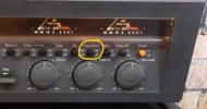
4) Dolby button is very "scratchy" when pressed and then the music peaks have "scratchy" noise. Dolby out is ok.
EDIT: Dolby switch required contact cleaner. Now no noise from the switch. But the RIGHT Dolby IC likely has damaged op amps (very bad distortion on music peaks!) and needs to be replaced. The left channel is fine, but the Dolby ICs are matched and must be replaced in pairs.
5) Lots of static in REW! (I know the reason... )
EDIT: This was because the MUTE signal wire from the Logic PCB was disconnected to get audio. See posts below. CORRECTED by reconnecting MUTE wire from Logic PCB.
6) Two VU bulbs burned out...
7) STOP and PLAY button bulbs burned out.
EDIT: now those bulbs have been swapped for the FF & REW bulbs. Replacing the STOP bulb fixed the original no audio issue for this thread!
And:
Does LINE OUT work? (Untested) EDIT: YES!
Does REC function work? (Untested) EDIT: Yes!
So the 580 is currently working better than the 480!
Record levels are very slightly unbalanced (1-2dB).
Now to see if REC will still work after removing the diagnostic jumper from R311? (Or maybe just leave it and remove completely the other jumper? )
)
Thanks again to dankik for all the help getting this far
Note to dankik and for future reference;
I now also know this is a VERY early very low S/N 580! Probably one of the last made of the few from the initial revision. The main PCB is the earliest "A" board. The boards shown in the manual are "B" ("previous 580" in manual) and the later one. That's why it's quite different.
1) The output level potentiometer is very "scratchy" and cuts volume at certain points.
EDIT: required disassembly and cleaning: FIXED!
2) It appears I re-soldered wires to the VU level meters on backwards during the earlier main PCB corrosion repairs.
The meters are moving in opposite direction! LOL!!EDIT: FIXED! Now the VUs work.
3) The "take up function at loading" is not working.
But maybe this VERY early 580 has no "take up function at loading." It also has no pressure pad lifter and no fancy right pressure roller assy.
EDIT: C428 does not exist on the logic board for this early 580. So no "take up function at loading." Guess I never noticed that until now! I'm more used to the 480.
4) Dolby button is very "scratchy" when pressed and then the music peaks have "scratchy" noise. Dolby out is ok.
EDIT: Dolby switch required contact cleaner. Now no noise from the switch. But the RIGHT Dolby IC likely has damaged op amps (very bad distortion on music peaks!) and needs to be replaced. The left channel is fine, but the Dolby ICs are matched and must be replaced in pairs.
5) Lots of static in REW! (I know the reason... )
EDIT: This was because the MUTE signal wire from the Logic PCB was disconnected to get audio. See posts below. CORRECTED by reconnecting MUTE wire from Logic PCB.
6) Two VU bulbs burned out...
7) STOP and PLAY button bulbs burned out.
EDIT: now those bulbs have been swapped for the FF & REW bulbs. Replacing the STOP bulb fixed the original no audio issue for this thread!
And:
Does LINE OUT work? (Untested) EDIT: YES!
Does REC function work? (Untested) EDIT: Yes!
So the 580 is currently working better than the 480!
Record levels are very slightly unbalanced (1-2dB).
Now to see if REC will still work after removing the diagnostic jumper from R311? (Or maybe just leave it and remove completely the other jumper?
)Thanks again to dankik for all the help getting this far
Note to dankik and for future reference;
I now also know this is a VERY early very low S/N 580! Probably one of the last made of the few from the initial revision. The main PCB is the earliest "A" board. The boards shown in the manual are "B" ("previous 580" in manual) and the later one. That's why it's quite different.
Last edited:
I was just on Google looking for 580 bulbs. Found a thread on Tapeheads. Seems the STOP button bulb could actually be the culprit that has taken WEEKS of troubleshooting to figure out!
Wish I had seen that thread previously! Dam web site that won't let me register without getting another email address...
I will swap bulb with another one, hopefully tomorrow, and see if it fully resolves the problem...
If that's actually the cause it's definitely a poor circuit design decision by Nakamichi...
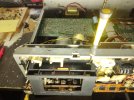
EDIT: Nakamichi Service Bulletin NR-0039 has a fix for this problem where the deck MUTEs when the stop button lamp burn out. The fix involves placing a 1K resistor across terminals 7-8 on the Logic PCB. Then, if the STOP button lamp burns out the deck will still have audio output. See the attached photo for an image of this fix. The resistor across terminals 7-8 on the Logic PCB is located at the top of the photo.
Wish I had seen that thread previously! Dam web site that won't let me register without getting another email address...
I will swap bulb with another one, hopefully tomorrow, and see if it fully resolves the problem...
If that's actually the cause it's definitely a poor circuit design decision by Nakamichi...
EDIT: Nakamichi Service Bulletin NR-0039 has a fix for this problem where the deck MUTEs when the stop button lamp burn out. The fix involves placing a 1K resistor across terminals 7-8 on the Logic PCB. Then, if the STOP button lamp burns out the deck will still have audio output. See the attached photo for an image of this fix. The resistor across terminals 7-8 on the Logic PCB is located at the top of the photo.
Attachments
Last edited:
This deck has been doing pretty good so far. So right now using it for tape testing while replacing the lamps in the 480...
But just had total dropout of RIGHT channel!
It's not the tape. FF brings back the right side for a second at full volume. Then it gets lower and sounds "muffled" like a pillow over the speaker. Then it goes to -40 dB and no volume from speaker but VU needle still wiggling a bit. FF brings it back again. REW likely does also. But not STOP then PLAY...
Currently it's doing better. But VU level is about 10dB lower compared to left channel.
I'd think the issue is likely a bad capacitor. But where?
Any ideas would be greatly appreciated!
But just had total dropout of RIGHT channel!
It's not the tape. FF brings back the right side for a second at full volume. Then it gets lower and sounds "muffled" like a pillow over the speaker. Then it goes to -40 dB and no volume from speaker but VU needle still wiggling a bit. FF brings it back again. REW likely does also. But not STOP then PLAY...
Currently it's doing better. But VU level is about 10dB lower compared to left channel.
I'd think the issue is likely a bad capacitor. But where?
Any ideas would be greatly appreciated!
Well, the right pinch roller likely needs replacement. The tape was previously moving up and down slightly on the right side, as noted previously. I haven't looked at that since the deck began working. But most likely it's still doing that. Also it has quite audible W&F when playing back a 400Hz test tone...
Where is a quality pinch roller available at these days? This deck also has a different right pinch roller than later model Naks with the standard transport. It's quite a bit larger than the left pinch roller.
The heads also likely need alignment along with all the other mechanical and electronic adjustments.
But, if it was one of the those items noted above, especially the pinch roller, wouldn't it tend to affect BOTH channels? And why has the issue only just appeared recently and then subsided again now? That certainly doesn't sound like it could be a head alignment issue!
Currently the right channel output is now approximately 5dB lower on the last tape. What's a way to know for certain what's causing the issue?
Where is a quality pinch roller available at these days? This deck also has a different right pinch roller than later model Naks with the standard transport. It's quite a bit larger than the left pinch roller.
The heads also likely need alignment along with all the other mechanical and electronic adjustments.
But, if it was one of the those items noted above, especially the pinch roller, wouldn't it tend to affect BOTH channels? And why has the issue only just appeared recently and then subsided again now? That certainly doesn't sound like it could be a head alignment issue!
Currently the right channel output is now approximately 5dB lower on the last tape. What's a way to know for certain what's causing the issue?
Sounds like the tape head is maybe not aligned or the pinch roller is bad and pulling the tape up/down off of the tape head.
dankik:
After going through a few more tapes I now definitely agree that it's a tape travel and/or tape issue.
The problem varies quite a bit. Sometimes it's both channels fading out slightly. The 480 lamps are now replaced. So I'm back to using it, and unfortunately, the same issue is happening on it sometimes.
The good news is that the right side of the tape is no longer moving on the 580
The left pressure roller assy. on the 580 is the same as the 480 and later Naks. Both that pressure roller and the two in the 480 are in excellent condition.
But the 580 right pressure roller is very shiny and worn even after lots of cleaning. Unfortunately that roller is significantly larger diameter than the later standard transport rollers. I have no idea if one is available or, if so, if the quality is decent.
Unfortunately any transport alignments will need to wait until the other work is complete and I have the proper tools...
I had to remove the 480 head plate to lubricate the pressure roller assys. But I doubt that significantly affected the head alignment. So it could also be that some of the recordings have somewhat degraded, as there are similar issues in both decks.
EDIT:
Now definitely appears to be some of the tapes
Previous tape with issues also was binding upon rewind. Next tape has initial signal loss and then fading at beginning where tape is most exposed.
UPDATE:
The newer tapes don't exhibit the issue, at least not to such a significant extent. So the issue is likely primarily just degraded tapes.
RM-580 play function works! But WITHOUT pressing any buttons! Simply waving the remote in front of the receiver starts playback!
No RM-580 buttons work...
Last edited:
There are degradation issues with many tapes. No severe tape travel or head alignment issues.Sounds like the tape head is maybe not aligned or the pinch roller is bad and pulling the tape up/down off of the tape head.
But after further investigation it appears the problem is with the right channel of the line amp section. The problem also unfortunately occurs on the 480. The headphone output is perfectly even on both decks. But right channel line output on both decks is very low and "muffled."

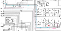
I traced the two paths for the R channel output on the 580 schematic (see below).The headphone output is perfectly even on both decks. But right channel line output on both decks is very low and "muffled."
Blue line goes to the output RCA, pink line goes to the headphone jack.
- Both come from the same source, IC302 pin 7. (red dotted circle)
- The signal splits up after passing through R253.
- From that point on, there are no other components in the signal path to the OUTPUT RCA.
- So, you need to check for cold solder joints, bad wire or solder between the board and RCA connector.
- You can Ohm out from the R channel RCA center conductor to R253 and you should have close to 0 Ohms.

Last edited:
Thanks!I traced the two paths for the R channel output on the 580 schematic (see below).
I'll need to double check the 580 line and HP signal outputs. It would really help to have a VTVM to measure the signal levels!
The 580 is different than the 480. On the 480 the signal goes to two separate amps. I'll look closer later at the 480 schematic. But the block diagram shows separate line and headphone amps.
The problem is more pronounced on the 480. The 580 has it to a lesser extent. It could be different issues such as a head alignment issue on the 580. On the 480, however, it's definitely not a transport issue.
That's the first thing I did, of course. The weak and muffled channel then changes sides. Connecting the same RCA cable to the tuner restores full volume to both channels with no "muffled" sound. The 333Hz test tone from the tuner is even on both channels.Please check your RCA cable to make sure that it is good. You can swap L & R channels on one end, then both ends, and see if the weak channel changes sides.
Last edited:
The 480 is similar to the 580. The headphone output takes the same Line Out signal and goes through one additional amplification stage before going to the headphone jack. Since you say that the headphone output is good, then the output from the first amplification stage must be because it is common to both the headphone output and line output.The 580 is different than the 480. On the 480 the signal goes to two separate amps. I'll look closer later at the 480 schematic. But the block diagram shows separate line and headphone amps.
The ONLY difference is that the line out goes through one more capacitor (C245) before going to the Line Out RCA jack.
Check C245 (C145) to make sure it is good. You can also check the board traces and solder.