

You are using an out of date browser. It may not display this or other websites correctly.
You should upgrade or use an alternative browser.
You should upgrade or use an alternative browser.
Nakamichi 580 no audio at RCAs & headphone jack
- Thread starter gnexus
- Start date
The signal was directly from the tuner to the amp input. Haven't tried yet to connect it to the tape deck. So the tuner definitely has issues. But that's not surprising. I already knew the sensitivity was crap.You can swap L and R channels from the tuner to the tape deck to see if the problem switches channels or if there is a problem with your tuner.
That tuner is the very last of my worries actually. But I want a better tuner anyway at some point. So will need to sell it. The sensitivity doesn't matter so much. I can always just suggest the buyer get a better antenna
 But if the channels are uneven then it needs work before selling it.
The transistors and capacitors arrived today. So I got to component swapping. Unfortunately it didn't really seem to change much in the bias circuit! It seems I really don't understand that circuit! Or something is really screwy...
Replaced components:
C311
Q301
Q302
Q311
I was being stupid and didn't check the voltages until after replacing everything but Q311. Voltage at R318 and the long jumper were at 0 to -7V and varying a lot after replacement of all those.
I replaced Q311 because I had one, and because the PCB traces has been previously repaired for it. So it could have been overheated by the soldering iron.
Voltages now after replacing Q311 are as follows:
(In STOP mode)
Pin 1 0V (gnd)
Pin 2 -12.3
Pin 3 +12
Pin 14 +11.42 (goes to 0V in REC)
R318 +11.41
Q303
(b) +11.4
(e) +12
(c) -11.8
L301 -11.8
R317 -11.8
Q302
(b) -11.8
(e) -12.3
(c) -11.8
Q302
(b) -11.8
(e) -12.3
(c) -11.8
C311
(+) -11.8
(-) -12.3
EDIT:
Ok. Somehow I didn't get proper readings the first time! Pin 14 wasn't changing in REC. The voltages are actually correct in RECORD mode! The manual doesn't note the fact that the shown voltages are for REC mode.
But that also means that, on this board with the long jumper, that IC303(8) will be at -12V when not in REC! That doesn't seem right...
Replaced components:
C311
Q301
Q302
Q311
I was being stupid and didn't check the voltages until after replacing everything but Q311. Voltage at R318 and the long jumper were at 0 to -7V and varying a lot after replacement of all those.
I replaced Q311 because I had one, and because the PCB traces has been previously repaired for it. So it could have been overheated by the soldering iron.
Voltages now after replacing Q311 are as follows:
(In STOP mode)
Pin 1 0V (gnd)
Pin 2 -12.3
Pin 3 +12
Pin 14 +11.42 (goes to 0V in REC)
R318 +11.41
Q303
(b) +11.4
(e) +12
(c) -11.8
L301 -11.8
R317 -11.8
Q302
(b) -11.8
(e) -12.3
(c) -11.8
Q302
(b) -11.8
(e) -12.3
(c) -11.8
C311
(+) -11.8
(-) -12.3
EDIT:
Ok. Somehow I didn't get proper readings the first time! Pin 14 wasn't changing in REC. The voltages are actually correct in RECORD mode! The manual doesn't note the fact that the shown voltages are for REC mode.
But that also means that, on this board with the long jumper, that IC303(8) will be at -12V when not in REC! That doesn't seem right...
Last edited:
I'm getting 0.1 to 0.2VAC at C101 and C201 in PLAY with the 400Hz test tone tape.
So it appears there should be a signal at IC101(9) and IC201(9) unless those caps are bad.
It's a bit problematic using the test tape. The 400Hz tone is quite short. Then must rewind it and find start again in the 480. REC mode with the tuner would be easier and more conclusive.
Also: that tape is binding up somewhat...
EDIT:
Damn! It's mangled right near the 400Hz tone! Wonder if it was already like that? If so then that would explain the flutter on the 480. If not then the 580 killed it!
So it appears there should be a signal at IC101(9) and IC201(9) unless those caps are bad.
It's a bit problematic using the test tape. The 400Hz tone is quite short. Then must rewind it and find start again in the 480. REC mode with the tuner would be easier and more conclusive.
Also: that tape is binding up somewhat...
EDIT:
Damn! It's mangled right near the 400Hz tone! Wonder if it was already like that? If so then that would explain the flutter on the 480. If not then the 580 killed it!
Last edited:
I'm not getting any signal in REC at C101and C201. There's 0.2 VAC at the tuner output with 333 Hz test tone. Same at FC-2. But nothing at REC/PLAY switch outputs at RCA cable jumpers or at C101/201.
The REC/PLAY switch is actuated. I haven't yet checked the input side of the REC/PLAY switch.
The REC/PLAY switch is actuated. I haven't yet checked the input side of the REC/PLAY switch.
Last edited:

Forget tracing the signal for now. Turn off power and unplug the deck.
We will trace the input signal path using your DMM by measuring resistance (Ohms).
Clip one DMM lead on the Left Input RCA center conductor and use the other lead to follow the signal path.

We will trace the input signal path using your DMM by measuring resistance (Ohms).
Clip one DMM lead on the Left Input RCA center conductor and use the other lead to follow the signal path.
- Find the VR PCB connector FC-1, Pin 4. You should have continuity from the input RCA to this pin.
- Next, move the probe to Pin 1. You should read about 12k Ohms.
- Next, find R101 on the Main PCB. On one side you should measure the same resistance as on Pin 1. On the other side you should read about 12k+18k=30k Ohms.
dankik:
Thanks very much for that and for your very quick reply to post #45!
Wow! That's a very straightforward path to IC101(9)!
Hadn't yet had time to check the schematic. Will check both L& R signal paths tomorrow morning. But it seems a bit unlikely that both channels would not have continuity. Maybe instead the signal is getting diminished to the point where that meter can't detect it?
Thanks very much for that and for your very quick reply to post #45!
Wow! That's a very straightforward path to IC101(9)!
Hadn't yet had time to check the schematic. Will check both L& R signal paths tomorrow morning. But it seems a bit unlikely that both channels would not have continuity. Maybe instead the signal is getting diminished to the point where that meter can't detect it?
That's why we are going to measure resistance from the input to the pin 9 from point to point without using a signal input. This will tell us if there is a break in the path from input RCAs to the IC101, through the control. By the way, I think I got the Balance and Rec Level controls labeled correctly, but it may be the other way around.Maybe instead the signal is getting diminished to the point where that meter can't detect it?
I just traced the Left signal all the way from the Left RCA input to C101. There's quite a lot of resistance after going through the VR board. No wonder the DMM couldn't register a REC signal!
So here's what we currently have:
1) A 400 Hz signal (well 0.2VAC anyway) present at C101/201 during PLAY.
2) Continuity from Left RCA pin through both flat cables.
3) Varying resistance through the Left REC level pot (it's actually L&R input levels and an output level pot) and back out through FC-1(1) and then through a jumper and R101 and R102.
4) A good coax jumper cable to PLAY/REC switch.
5) A working PLAY/REC switch that I know for certain now definitely works.
6) A good coax jumper cable from PLAY/REC switch to C101.
I'd assume the right channel REC path is also ok. I can always check it later...
At this point it seems I need to check IC101. Need first to check pins 1 and 5 for gnd & voltage. Then, if I'm getting a signal to pin 9 in PLAY with 400Hz tone, wouldn't it be possible to hopefully see an output signal on the DMM in PLAY with 400Hz tone? (Or not, if IC101 is bad...)
ICs 101 and 102 are definitely suspect at this point because the voltages on the headphone and line out amp circuits matched perfectly with the ones in the manual. Also they are large ICs that likely could have easily been damaged by the corroded PCB traces before that was repaired.
So here's what we currently have:
1) A 400 Hz signal (well 0.2VAC anyway) present at C101/201 during PLAY.
2) Continuity from Left RCA pin through both flat cables.
3) Varying resistance through the Left REC level pot (it's actually L&R input levels and an output level pot) and back out through FC-1(1) and then through a jumper and R101 and R102.
4) A good coax jumper cable to PLAY/REC switch.
5) A working PLAY/REC switch that I know for certain now definitely works.
6) A good coax jumper cable from PLAY/REC switch to C101.
I'd assume the right channel REC path is also ok. I can always check it later...
At this point it seems I need to check IC101. Need first to check pins 1 and 5 for gnd & voltage. Then, if I'm getting a signal to pin 9 in PLAY with 400Hz tone, wouldn't it be possible to hopefully see an output signal on the DMM in PLAY with 400Hz tone? (Or not, if IC101 is bad...)
ICs 101 and 102 are definitely suspect at this point because the voltages on the headphone and line out amp circuits matched perfectly with the ones in the manual. Also they are large ICs that likely could have easily been damaged by the corroded PCB traces before that was repaired.
Last edited:
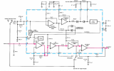
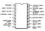
This DMM is not going to work for checking audio signals. This morning it's getting crazy readings in AC volts. It's varying between 0.1 and 4V. That is without the probes touching anything except the grounded PCB connected to negative probe. That reading changes constantly just by picking up the probe!
Anyway, DCV still works correctly. Here are the readings for IC101/201 power supply:
Pin 1 -9V
Pin 5 +8.7
Pin 8 -2.3
Those are quite different readings than what is specified in the uA7300PC datasheet. But they correspond correctly voltages in the 580 manual.
It appears I either need a better meter, or two new ICs to use as test replacements. Or both...
Anyway, DCV still works correctly. Here are the readings for IC101/201 power supply:
Pin 1 -9V
Pin 5 +8.7
Pin 8 -2.3
Those are quite different readings than what is specified in the uA7300PC datasheet. But they correspond correctly voltages in the 580 manual.
It appears I either need a better meter, or two new ICs to use as test replacements. Or both...
You can check these other voltages on the chip to see if there are any other problems.
I also saw that the schematic shows two pin 8s on the IC??? Need to look at the board layout to see which is real.
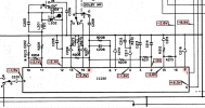
Looking at the board layout, it looks like pin 8 connects to R106, R107 (schematic error R407), R109, and C116.
So pin 8 connects to both the resistors and cap on the schematic.
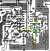
I also saw that the schematic shows two pin 8s on the IC??? Need to look at the board layout to see which is real.
Looking at the board layout, it looks like pin 8 connects to R106, R107 (schematic error R407), R109, and C116.
So pin 8 connects to both the resistors and cap on the schematic.
Last edited:

tadawson
Well-Known Member
High impedance input, and magnetic (AC) fields in the space coupling into the test leads will do that - it's normal. If you get zero with the leads connected together, it's likely fine.This DMM is not going to work for checking audio signals. This morning it's getting crazy readings in AC volts. It's varying between 0.1 and 4V. That is without the probes touching anything except the grounded PCB connected to negative probe. That reading changes constantly just by picking up the probe!
Anyway, DCV still works correctly. Here are the readings for IC101/201 power supply:
Pin 1 -9V
Pin 5 +8.7
Pin 8 -2.3
Those are quite different readings than what is specified in the uA7300PC datasheet. But they correspond correctly voltages in the 580 manual.
It appears I either need a better meter, or two new ICs to use as test replacements. Or both...
Yeah. I'm certain the DMM is fine. It just can't reliably read very low AC voltages like the audio signals here.High impedance input, and magnetic (AC) fields in the space coupling into the test leads will do that - it's normal. If you get zero with the leads connected together, it's likely fine.
Need better test equipment for audio work...
A seller in China has LA2730 ICs for a good price. Those are supposedly a good upgrade anyway. So just ordered 6. Then can use one as a test replacement, and also as upgrades if they work since they are supposedly much better than the uA7300PC.
Those will take quite a while to arrive from China. So lots of time for troubleshooting and searching for low cost test equipment in the interim.
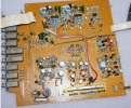
Take a look at this first. On the Main PCB there is a long Record/Play switch (outlined in dotted yellow line in the photo), SW301. The function of the switch is to switch parts of the circuit between record and play. The contacts of this switch get dirty and oxidized, or the cable that switches the position of the switch is not working, or hardened grease prevents it from moving back/forth.
- With power off, locate the switch and carefully see if you can move it back/forth a little
- If that is OK, then with power on and cassette in, see if the switch changes position when you go between Play and Rec modes
- If it doesn't move, then it could be in the wrong position cutting off the audio signal from going through.
- The switch as multiple contacts so it switches a lot of signal paths.
It was previously noted in post #49 item 5 that the switch is now fully tested and works fine.Take a look at this first. On the Main PCB there is a long Record/Play switch (outlined in dotted yellow line in the photo), SW301.
tadawson
Well-Known Member
Consider investing in a rudimentary oscilloscope. You don't need much to trace audio . . .Yeah. I'm certain the DMM is fine. It just can't reliably read very low AC voltages like the audio signals here.
Need better test equipment for audio work...
A seller in China has LA2730 ICs for a good price. Those are supposedly a good upgrade anyway. So just ordered 6. Then can use one as a test replacement, and also as upgrades if they work since they are supposedly much better than the uA7300PC.
Those will take quite a while to arrive from China. So lots of time for troubleshooting and searching for low cost test equipment in the interim.
No doubt! It's on the list...Consider investing in a rudimentary oscilloscope. You don't need much to trace audio . . .
But so are a lot of other things... Many of my tools were destroyed in the 40' shipping container where this deck was stored, along with most of my clothes and two show cars, when hurricane Harvey hit and flooded the container with 4' of water. Still trying to recover many years later...
On a different 580 topic:
Just tried the music test cassette (currently in need of new leaders) again with VU meters attached. Nothing yet has changed, of course... DEAD...
But I did notice now that the cassette case assy. seems slightly warped on the right side. It takes significant pressure on the left side of the case to get it to latch. It's impossible to latch it by pressing on the right side.
Once latched the left side is tightly pressed against the mechanism cover plate. But the right side remains approx. 2.5 mm away from the cover plate. This situation causes the right reel hub to occasionally, or sometimes often, jump in the cassette hub during FF and PLAY.
There's no obvious adjustment for this issue. On my 480 there were actually two washers in between the right cassette case bracket and the mechanism chassis to space it out further. Turns out those were necessary to get the cassette case to close smoothly. But here there are no washers and the bracket needs to go in the opposite direction.
Either the cassette case must go inwards 2.5 mm, or the right reel hub needs to move outward a similar amount to resolve the issue. I could put washers between the left bracket and the chassis to make the distance even on both sides. But that would likely move the cassette case outward more on the right.
Any ideas on a fix?
Also: the right side of the cassette moves up and down very slightly (1 mm or less) during playback. Does that mean the right reel hub is slightly bent? (how could a plastic hub bend?)
Just tried the music test cassette (currently in need of new leaders) again with VU meters attached. Nothing yet has changed, of course... DEAD...
But I did notice now that the cassette case assy. seems slightly warped on the right side. It takes significant pressure on the left side of the case to get it to latch. It's impossible to latch it by pressing on the right side.
Once latched the left side is tightly pressed against the mechanism cover plate. But the right side remains approx. 2.5 mm away from the cover plate. This situation causes the right reel hub to occasionally, or sometimes often, jump in the cassette hub during FF and PLAY.
There's no obvious adjustment for this issue. On my 480 there were actually two washers in between the right cassette case bracket and the mechanism chassis to space it out further. Turns out those were necessary to get the cassette case to close smoothly. But here there are no washers and the bracket needs to go in the opposite direction.
Either the cassette case must go inwards 2.5 mm, or the right reel hub needs to move outward a similar amount to resolve the issue. I could put washers between the left bracket and the chassis to make the distance even on both sides. But that would likely move the cassette case outward more on the right.
Any ideas on a fix?
Also: the right side of the cassette moves up and down very slightly (1 mm or less) during playback. Does that mean the right reel hub is slightly bent? (how could a plastic hub bend?)