• The move to the new server is done. There are some software and database maintenance updates in process. This has us passing the hat around to help out. We appreciate any donations. Seriously, even a dollar helps. The payment page may be found here - https://www.audiokarma.org/support.html

Need a AR-XA measurement please...

I appreciate the input guys!

I can easily fashion an aluminum plate to affix the arm mount to the t-bar. But with the arm pivot offset to one side of the t-bar the only way I can think of to compensate for the torsion would be to make a 'T' shape plate with a mass opposite the arm on the other side of the t-bar. The problem with that approach is the limitations of the burl shape and the limitation of my brain to determine where to locate the balancing mass and how much mass is needed? Then the arm and the balancing mass is going to play havoc with the spring rate as I imagine it might triple the original arm mass load on the t-bar?

This is fun stuff!
 
I don't see any other way than to extend the arm bracket end outward and provide an in-line cut-out in the burl base for the arm mount. You would not want to offset the mass of the arm assembly from the line of the 'T' as it would introduce torque forces that would encourage difficult-to-quell resonances into the substructure. AR got the best of the most out of the relatively flimsy substructure casting in the original design intent. A project this esthetically ambitious should have assurance it will sound as good as it looks.
If you could cut out the burl and then remount it to the arm extension as an arm mount platform with sufficient clearance you may be able to maintain most of your esthetic intent. You will definitely have to correct the suspension for the added mass along with the arm and extension.
BTW, got a pic of the arm to go on it?
 
Last edited:
I appreciate the input guys!

I can easily fashion an aluminum plate to affix the arm mount to the t-bar. But with the arm pivot offset to one side of the t-bar the only way I can think of to compensate for the torsion would be to make a 'T' shape plate with a mass opposite the arm on the other side of the t-bar. The problem with that approach is the limitations of the burl shape and the limitation of my brain to determine where to locate the balancing mass and how much mass is needed? Then the arm and the balancing mass is going to play havoc with the spring rate as I imagine it might triple the original arm mass load on the t-bar?

This is fun stuff!

no, you can off-set the arm and counter off-set the mass. You have to understand the center of gravity in an AR suspension is not below the platter spindle. you have room in the burl to do this. I'm with Pio on this that rigidly mounting the arm and with the supension allowed to move slightly due to the springs, you could/would get into a scrubbing issue of the stylus on the album. Note to Pio. that T-bar isn't really flimsy. The first generation stamped steel one was. The cast assembly is quite rigid.
 
Do you know of a good source for lead to use as mass? Is it enough to assume that the arms mass is centered on the pivot point, even though the effective mass of the arm forward of the pivot will be ~ 16 grams?

Sounds like I should order some Linn springs.
 
Do you know of a good source for lead to use as mass? Is it enough to assume that the arms mass is centered on the pivot point, even though the effective mass of the arm forward of the pivot will be ~ 16 grams?

Sounds like I should order some Linn springs.

Tire balancing weights are the most readily available source of lead, highly malleable and low melting point.
 
--snip-- Note to Pio. that T-bar isn't really flimsy. The first generation stamped steel one was. The cast assembly is quite rigid.

I passed on a nice AR TT on the 'bay to examine 'cuz I had the H-K project in hand and no spare change, haven't seen the innards of them personally tho' the H-K is likely more rigid and the Linn KEEL the benchmark of rigidity. It's relative. The H-K's 'rigid' sub-plate should ring like the frying pan it resembles without damping and it's other mid-bass resonance from the "tuning fork" formed between the counterbalance and arm off the platter's mass is a solvable problem as well that I addressed with the counterbalance floating dead mass load damping remount. No significant added mass to alter suspension parameters and ugly goop, much more elegant and effective than Moretite. The arm gimbal is basically a nice broad bearing barrel end-mounted in a tuning fork that literally screams for damping, easily applied with dead mass load damping.. This also damps the arm resonances as well as terminating the upper end of the pillar with dead mass damping. Again, elegant.
The interesting thing about the simple mods to the H-K is that the design provides for them almost as if they just decided not to finish the job right for unknown reasons.

The point of this posting;
You can pretty much play around thumping things on the TT and model the thing in your head and fool with it to find resonant structures ("tuning forks") and model ways of dealing with them. This is the method I use and it works most of the time. A stethoscope on the arm gimbal and base can show re-activeness of the cart/ arm/pillar/mounting. This is one area where achieving a non-peaky low-level result is very important IMO and the major reason for differences between arms. Dead-mass load damping of the gimbal/pillar could pay huge dividends here toward neutralizing the sound but almost no-one does it. I'm also of the school that a cart needs inherent reactive-resistant mass loading to direct the energy into the transducer and not down the arm and pillar into the baseplate and delayed back to the cart. Heavier is better regardless of compliance for lifelike transient response IMO. Grounding the record solidly to a semi-resilient or hard mat with a heavy-ish damped platter serves the same purpose, I do not care for the idea of mat arrangements that 'float' the disc unsupported by hard backing, rendering them both microphonic and reactive which while perhaps euphonic definitely not neutral. H-K got that right better than most with their slightly dished hard mat/weight arrangement.
 
Last edited:
no, you can off-set the arm and counter off-set the mass. You have to understand the center of gravity in an AR suspension is not below the platter spindle. you have room in the burl to do this.

IIRC, the center of mass should be equidistant between the springs, about where the large hole in the longer t-bar arm is? Are the original springs different spring rates? What about the Linn springs?
 
IIRC, the center of mass should be equidistant between the springs, about where the large hole in the longer t-bar arm is? Are the original springs different spring rates? What about the Linn springs?

Of course this will add considerably to the mass of the arm end of the suspension but it'd work fine. I'd dead-mount the added mass as per the H-K.
 
IIRC, the center of mass should be equidistant between the springs, about where the large hole in the longer t-bar arm is? Are the original springs different spring rates? What about the Linn springs?

Yes, the center mass of the subchassis is where the large center hole is.
It is offset from center mass of platter torque for a reason. The platter torque is holding the "short end of the stick" in trying to move the subchassis in opposite direction during heavy transient attack. It doesn't matter much if you move the angle of the arm mount some as long as you counter balance opposite side of that center mass area. You need to set all this up outside the plinth your making. Email me and I'll show you how I set suspensions up outside the table. I'm betting you should go to the Linn spring set due to all the extra mass you'll be adding. Generally it takes 3 lbs of additonal mass on an XA subchassis when adding linn springs to get them in proper tune. not enough mass to compression rating and the frquency of jounce is too fast, and more like an up/down V instead of a nice synewave jounce.
 
I was considering using the XA top plate to set it up outside the burl, but I'll send you an email to discuss it. Thanks again.
 
Thanks again to Ben, my pretty Luxman tonearm showed up yesterday! The total weight without cartridge and the extension plate will be approx. 14 ounces.

Marc, do you know off-hand what the spring rate for the Linn springs is? Looks like I'm going to end up with around 5 pounds of parts hanging on them with platter, t-bar and tonearm. I've also ordered a 1.5 pound brass weight to offset the torsional arm mass on the t-bar.

On that subject, I noticed that the standard Linn setup has the armboard mounting at 90 degrees to the long end of its "T". Obviously the tonearm is mounted offset to the t-bar quite a bit, so how important can this torsion be?
 
Thanks again to Ben, my pretty Luxman tonearm showed up yesterday! The total weight without cartridge and the extension plate will be approx. 14 ounces.

Marc, do you know off-hand what the spring rate for the Linn springs is? Looks like I'm going to end up with around 5 pounds of parts hanging on them with platter, t-bar and tonearm. I've also ordered a 1.5 pound brass weight to offset the torsional arm mass on the t-bar.

On that subject, I noticed that the standard Linn setup has the armboard mounting at 90 degrees to the long end of its "T". Obviously the tonearm is mounted offset to the t-bar quite a bit, so how important can this torsion be?

Hi, the linn springs (3) will support roughly 8 1/2 pounds before they are compressed beyond tune.

The linn table has two springs at the tonearm end and one beyond the platter. Just opposite how AR did it. The offsets around the springs, as long as you retain the center mass point of the subchassis, it really doesn't matter where the springs in relation to off-set mass are. Provided all three planes are parallel. Platters, subchassis, bottom of the springs. As an example on the later AR tables the arm spring is moved in some to allow the use of armboards, that spring is of a higher rate to accommodate the increase in mass at that end, yet retaing the same center of gravity.
I believe the set up jig I use would make it easier on you than mounting on studs and going back and forth with mass loading.......the offer on the jig loan still stands. Besides, the perches needed to use the jig can be used as the spring perch....and these garrantee the springs will be centered to the studs. The lower grommets you have now, or will get with a linn spring kit do not garrantee center.....take a look at your old ones just to see how off center they were. The suspension will not "piston" properly if the springs are off center. No masters degree needed in the "black arts" with my system. :D

Oh, and we haven't even discussed your main bearing,thrust plate and spindle yet :smoke:
 
You're making this interesting Marc! Drop me an email with a list of parts you think I'll need. The grommets are definately looking sad. The foam rotted away, and what's the deal with the copper colored tubes in the grommets? Seems like they would be another source of vibration.

I've still got plenty to do before tuning, so let me get my head around this before I borrow your gear. Thanks a bunch for the offer!
 
BTW, I did polish the spindle in a cross-hatch pattern with 1000 wet dry and cleaned the main bearing per the youtube video. I've added a hardened steel thrust plate that was polished with 1000 WD and magic eraser. It's actually a 3/8" drill slug that's 1/2" long, otherwise I can't get enough clearance for the subplatter above the burl. There wasn't any sort of thrust plate at the bottom of the bearing tube when I got the turntable, should there have been?
 
Hi Jim, There should have been a worn out flat delrin disk at the bottom. in off white color. What you need to do is polish the ball end of your spindle back to round, and to a 1 micron finish. I can send you a set of photos to show how I do it. and if you need the papers down to 1 micron, I can send you those as well.
 
That would be great! Looks like I've got more to do, from the looks of it...

I need your direction for proper cross-hatch work on the spindle as well. I can't see anything in the bottom of the spindle well, it just looks like pot metal.
 

Attachments

  • ballend1.jpg
    ballend1.jpg
    74.5 KB · Views: 61
  • ballend2.jpg
    ballend2.jpg
    59.2 KB · Views: 55
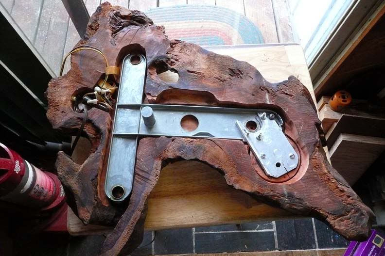
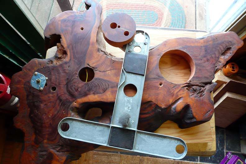
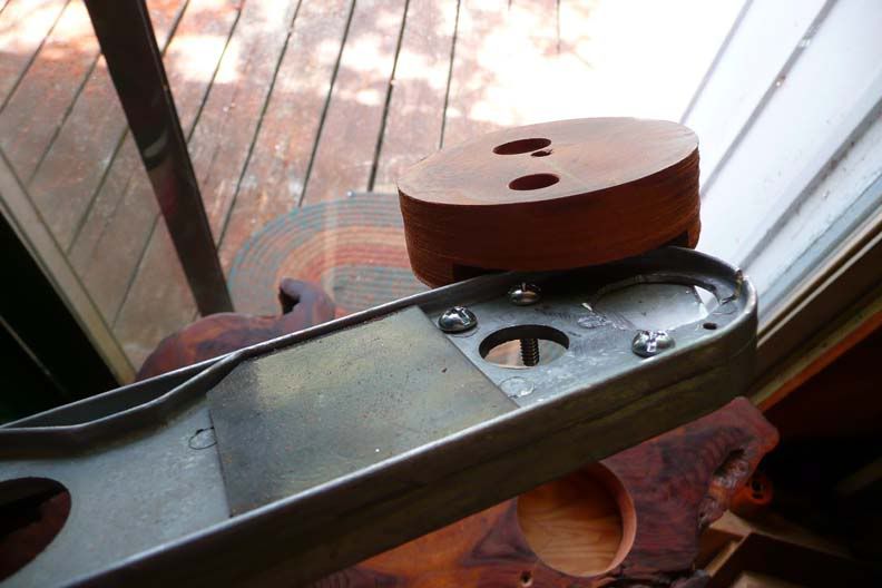
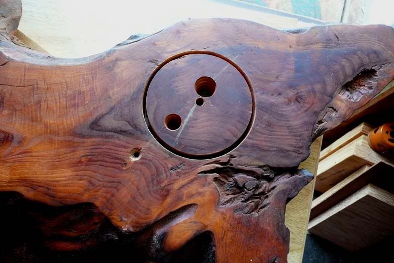
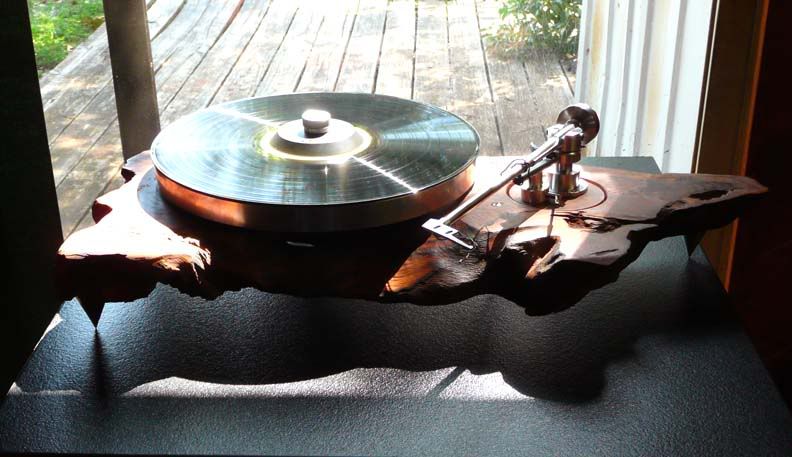
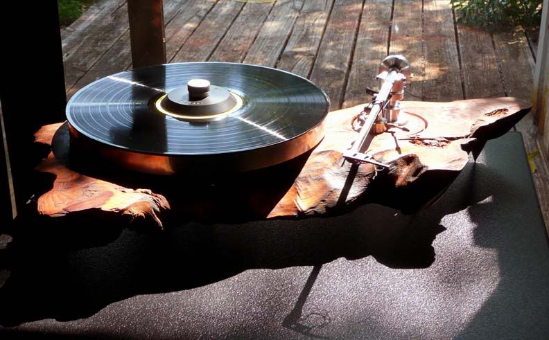
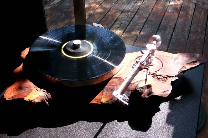
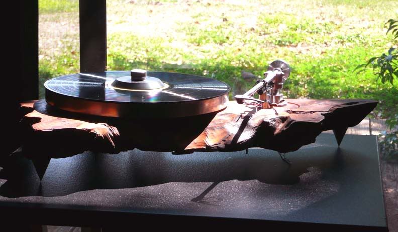
Much more progress today! I worried several issues all week, primarily the cutting of the top deck for the tonearm and lifter and the balance weights to get it sprung right. Well, the springs I ordered haven't arrived yet but I have the arm and the spikes so I got to work early and here is the current condition!

Burl9.jpg


Burl10.jpg


Burl11.jpg


Burl12.jpg


Burl13.jpg


Burl14.jpg


Burl15.jpg


Burl16.jpg


So, lots left to do, springs balance, build the HDPE skirt (so there's someplace to mount the switch and the rca jacks), and wire the arm. Loads of fun, but I'm pooped! :D
 
Back
Top Bottom