• Please note that Audiokarma will be offline briefly for updates early on Monday morning, September 28th.

Need Bias Current Help with Sansui AU-20000 (0 mv)

Well done, that's solid.

Just a few observations before maybe giving this a break:

TR10 and TR11, take out the tab washer from underneath the head of the screw. It's not necessary, more important to have direct electrical connection between the screw and the transistor tab.

TR06 you've listed as KSC945. Check it's actually KSC945C according to the way it's inserted.

Check VR02 as mentioned by @Hyperion for correct value and operation.
 
Last edited:
I got frustrated and ended up feeding audio to see what is on output. i connected an old speaker that I had, and surprisingly there is audio on the speakers. not sure how bad it sounds, but ok on low volume. still 0mV on current Bias. Pin 2 & 4

Post #21: yes it is KSC954C sorry for the confusion. I took out all the transistors and tested them separately and they seem ok.

Thanks a lot I’ll give it a brake for now!
 
Last edited:
voltage at 27 and 28 on each of the F-2497 : is 60mV, both sides
Working back from there, measure the resistors R35 and R36 on F-2507 to verify they are no higher than 4.7Ω, sometimes they can be inadvertently replaced with 4.7KΩ, (only applies if replaced on both boards).
 
Last edited:
If nothing comes to light after checking R35 and R36, test the transistors TR10 and and TR11 by measuring the base and emitter voltages.

TR10 base = 1.1V
TR10 emitter = 0.5V

TR11 base = -1.1V
TR11 emitter = -0.5V

You may need to adjust VR02 to see these values, start with VR02 fully CCW and adjust upward.
 
Here is my swap list:

View attachment 3244117

I am now doing what you recommended in Post #18. Again thanks a lot, this has been very helpful.
Couple of observations. replacing 2SA818/2SC1628 with KSA1220/KSC2690 not optimal especially for TR04. Not sure why you did not use KSC3503/KSA1381 for that position as those are low Cob parts. In the overcurrent circuitry(TR06/TR07) originally complimentary pair 2sc945/2sa733 was used and note recommended hfe grade was P or Q where hfe grade is below 400. You replaced tr07 with ksa992 which often has hfe above 400. for me more logical whould be the use of similar to originals complimentary pair ksc1815yta/ksa1015yta making sure that both 1815 and 1015 have hfe above 135 (as original 945/733 q grade starts from 135.

interesting contrast i see in driver transistors choice in service manual . It could be 2SA839/2SC1669. or 2SB537/2SD382. What is interesting that ft of first pair is 3Mhz and ft of second pair is 30Mhz !!! To be honest i would choose MJE15032/33 as a replacement here as higher ft driver pair at least theoretically should translate to lower TIM distortions. But in reality i would leave driver transistors alone if they were intact.
 
Last edited:
If nothing comes to light after checking R35 and R36, test the transistors TR10 and and TR11 by measuring the base and emitter voltages.

TR10 base = 1.1V
TR10 emitter = 0.5V

TR11 base = -1.1V
TR11 emitter = -0.5V

You may need to adjust VR02 to see these values, start with VR02 fully CCW and adjust upward.
I can get these voltages exactly by tuning VR02 but pin 2,4 still read 0mV DC


I even took one of the drivers and swapped all the transistors with original that I took out and the equation does not change. I tested all the older transistors before I put them on the driver. 0mV DC still on pin 2,4

It only has any voltage when there is audio playing.
 
Checked all resistors by taking them out one by one. Everything looks good.


Is it possible for the amp to run even if one or many outputs transistors are bad ?
 
Last edited:
I can get these voltages exactly by tuning VR02 but pin 2,4 still read 0mV DC
voltage at 27 and 28 on each of the F-2497 : is 60mV, both sides

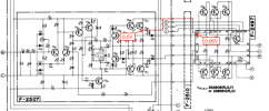
Let's see those measurements on the schematic:

Screen Shot 2024-07-07 at 8.49.37 pm.png


Looking at just the upper part of the circuit, your voltage reading on the emitter of TR10 of ~0.5V tells us the driver is behaving as expected. You should see a little less than 0.5V on the other side of R35, given you verified its value.

If you have 0.5V at R35 but only 0.06V at 28 then something is not right with the connections. Check the condition of the board connector blocks and pins, Solder pads around connector pins may be weakened, lifted or torn from repeated fitting and removal of the driver boards.

(27/28 is connected to the base of the output transistors. Approx +/-0.5V is needed to turn them on. Once current starts to flow through the emitter resistors hopefully then you will get a proper reading across 2 and 4)
 
Last edited:
Let's see those measurements on the schematic:

View attachment 3245171


Looking at just the upper part of the circuit, your voltage reading on the emitter of TR10 of ~0.5V tells us the driver is behaving as expected. You should see a little less than 0.5V on the other side of R35, given you verified its value.

If you have 0.5V at R35 but only 0.06V at 28 then something is not right with the connections. Check the condition of the board connector blocks and pins, Solder pads around connector pins may be weakened, lifted or torn from repeated fitting and removal of the driver boards.

(27/28 is connected to the base of the output transistors. Approx +/-0.5V is needed to turn them on. Once current starts to flow through the emitter resistors hopefully then you will get a proper reading across 2 and 4)
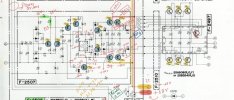
Tested all connections. Here is the voltage test results.
 

Attachments

Follow the voltage on the TR10/11 emitter and try to find the point where it drops out before reaching 27/28 (F-2497).

If necessary, de-solder the connections at 27 28, to help isolate the problem.
 
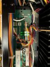
If you don't have any luck with this, post a close-up photo of F-2512 in the area where the wires from F-2497 join to the driver board connector pins.
 
Follow the voltage on the TR10/11 emitter and try to find the point where it drops out before reaching 27/28 (F-2497).

If necessary, de-solder the connections at 27 28, to help isolate the problem.
Will do, thank you!
 

Attachments

  • IMG_9318.jpeg
    IMG_9318.jpeg
    108.7 KB · Views: 18
  • IMG_9314.jpeg
    IMG_9314.jpeg
    132.7 KB · Views: 18
  • IMG_9316.jpeg
    IMG_9316.jpeg
    121.9 KB · Views: 18
I don't think they are relevant to your issue, they are current steering diodes for the VI limiter, (is my guess).
 
With F-2510 boards removed, check for voltage directly off the board pins (where the red and black wires connect). .. with driver board installed.

IMG_9316.jpeg
 
Last edited:
Is it possible for the amp to run even if one or many outputs transistors are bad ?

If the amp was working beforehand it's likely the output transistors are okay. Output transistors usually fail through a collector - emitter short. In this amp, it will probably cause the main fuse to blow. When chasing these sorts of issues, have VR02 turned to a minimum each time you test a driver board to avoid the risk of damaging the output transistors.
 
  • Like
Reactions: Utk
… any progress on resolving the bias problem? It would be interesting to know what you find.
 
Last edited:
  • Like
Reactions: Utk
Back
Top Bottom