

Hey everyone,
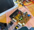
I made some custom wires to bring out both driver boards so I could test them on my desk. After swapping the VD1212 with the original diode on the board and some Transistors, everything seems to have started working. However, I noticed that the Bias setting for 35mV is at the very edge of the 1K VR02 in the clockwise direction. It ramps up very quickly, and I only get about half a turn on my 25 or 22-turn pot to reach the correct value and it's at like at the 3rd turn from the end. It seems like the scaling might have drifted over time. Not sure if this is because the transistors are old because all the Resistors are within 1% of the spech.
I also changed some transistors. Here is the new SUB_LIST: The last CHANGED_TO Column is what I have now:

One question:
I set the bias and bias current after the amp was warm, but when it cold starts, there is a significant DC offset that dissipates in about 4-5 seconds. However, the speaker relay usually clicks in within 2 seconds. If the speaker selector is on System A, for example, I hear a loud pop from the speakers when RL01 clicks. If I have the selector set to 'off' on power up and then switch to Speaker A, the pop isn't there.
Additionally, I noticed that the first cold start pop is much louder than subsequent ones, which get fainter as I keep turning the amp off and on, but it doesn't completely go away. I've swapped everything but the main filter caps and the cap on the power switch. The DC offset at the speaker terminal poses a problem, as it takes some time to settle, and I suspect RL01 clicks too quickly. I've made sure to replace the relays and caps on the F-2511 board with the exact values that were there before.
Lastly, I want to thank everyone for all the help they have provided. I couldn't have done it without your Help!
I made some custom wires to bring out both driver boards so I could test them on my desk. After swapping the VD1212 with the original diode on the board and some Transistors, everything seems to have started working. However, I noticed that the Bias setting for 35mV is at the very edge of the 1K VR02 in the clockwise direction. It ramps up very quickly, and I only get about half a turn on my 25 or 22-turn pot to reach the correct value and it's at like at the 3rd turn from the end. It seems like the scaling might have drifted over time. Not sure if this is because the transistors are old because all the Resistors are within 1% of the spech.
I also changed some transistors. Here is the new SUB_LIST: The last CHANGED_TO Column is what I have now:
One question:
I set the bias and bias current after the amp was warm, but when it cold starts, there is a significant DC offset that dissipates in about 4-5 seconds. However, the speaker relay usually clicks in within 2 seconds. If the speaker selector is on System A, for example, I hear a loud pop from the speakers when RL01 clicks. If I have the selector set to 'off' on power up and then switch to Speaker A, the pop isn't there.
Additionally, I noticed that the first cold start pop is much louder than subsequent ones, which get fainter as I keep turning the amp off and on, but it doesn't completely go away. I've swapped everything but the main filter caps and the cap on the power switch. The DC offset at the speaker terminal poses a problem, as it takes some time to settle, and I suspect RL01 clicks too quickly. I've made sure to replace the relays and caps on the F-2511 board with the exact values that were there before.
Lastly, I want to thank everyone for all the help they have provided. I couldn't have done it without your Help!

