• The move to the new server is done. There are some software and database maintenance updates in process. This has us passing the hat around to help out. We appreciate any donations. Seriously, even a dollar helps. The payment page may be found here - https://www.audiokarma.org/support.html

Need help replacing KR-5600 bridge rectifier M4B-3

tusntuk2

Active Member
Need help replacing KR-5600 bridge rectifier S5VB20. I used dlucy's suggestion of a 400v/35a bridge on a previous KA-3500 restore, but I found it larger than the original. Space is tighter in the 5600. Could I use something like a KBPC804PBF? It's 400v/8a (Vishay). I plan to use 10,000uf caps to replace the 7,500uf originals. I'm not sure what is most important here - heat? - initial surge? - physical layout? You guys are the best! Thanks.
 
Register to hide this ad
When you turn the power on, the power reservoir caps draw as much current as they can to "fill up". This is called inrush current.

When you increase the capacitance (how much a cap can hold) over the stock value, you are increasing the amount of inrush current that cap "asks" for. That said, the inrush is very brief. After that, the current draw is... well... normal. (You can now tell how little I actually understand about all this.)

The other components between the power reservoir cap(s) and the AC cord will also need to be able to handle the increased current. Fuses, transformer, other caps, the bridge or diodes that rectify the AC into DC to feed the power reservoir caps.

I have never had a problem with inrush from a larger-than-stock capacitance, but I also upgrade the diodes/bridge and other caps.
 
Thank you gentlemen! I watch the larger mains caps debate with interest, as I have had both good and bad luck with it. I recently completed restoring a KA-3500 (LOVE that amp!) with larger main caps, and used dlucy's (rather large) rectifier. While seeming to be a bit of overkill at 35A, the amp sounds awesome and has serious power hiding in the volume control. I also boosted the input caps (Ce1,2) and two tone caps, so it does have BASS, and it kicks it.

On the other hand, the last KR-5600 I did I used larger main caps but did not change the rectifier. I had trouble with apparent oscillations when the bass was kicked up. Don't know if it was related. It calmed down with a better pass regulator (Qe25). I did not bypass the mains - would that have made the difference? I plan to use 1uf/250v bypass caps on this KR-5600 project, as well as bigger 10k main caps and a new rectifier and regulator. I will report the results.
 
I recently completed restoring a KA-3500 (LOVE that amp!) with larger main caps, and used dlucy's (rather large) rectifier. While seeming to be a bit of overkill at 35A, the amp sounds awesome and has serious power hiding in the volume control.

I thought we had agreed to not talk about the size of my rectifier.... ;)

Would Vishay's VS-KBPC804 (400V 8A) bridge be a better fit?
 
LOL! You're good, Doug...

Well that's what I chose just looking at specs. (#1) Turns out the 5600 has an M4B-3 rectifier, not the S5VB20, but right now I have not reopened the amp to actually see it. The Vishay..804 is quite small, less than 16mm. Might make some funky spider leg leads to the board, no? I'll take it apart to see eyes on.
 
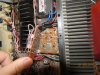
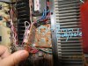
Whoa - back to the drawing board. The M4B-3 is a large heat sink affair with a small round center where the poles are. Forgot that, I didn't change it last time. Hmmm, reconsidering the jump from the original 7,500 caps to 10,000. Just had the 10's in stock, and it seemed reasonable.
 
Whoa - back to the drawing board. The M4B-3 is a large heat sink affair with a small round center where the poles are. Forgot that, I didn't change it last time. Hmmm, reconsidering the jump from the original 7,500 caps to 10,000. Just had the 10's in stock, and it seemed reasonable.

10,000 uF caps seem like a fine upgrade. What is the amount of space you have available? Have you checked the dimensions in the VS-KBPC804 datasheet?
 
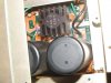
The pcb with the cans and rectal thermometer hangs upside down under the voltage regulation board . The old rectifier is pretty large, the smaller Vishay would easily fit. I would need to bend the legs inward to connect. Trying to visualize...(my goodness this is sounding BAD!).

I did check the datasheet (see #7) and it would fit, just need to bend the leads a lot. They need to fit in about a 1" circle.

And 7,500uf/50v caps are hard to replace, I think this was covered before in AK. I'll go look some more. I want to use the 10K caps if I can. I know they fit, I've used them before.
 
(Sorry, got carried away there. Spell checker blues, you know.). Surprisingly enough, the little size of the VS-KBPC804 might just be the correct solution to the problem, The leads are about 11mm apart, which translates to a circle of just bigger than 1/2". I'll need to pull the boards out to measure exactly, but this guess might be welcome serendipity. Perhaps I should pick a higher amperage?
 
Perhaps I should pick a higher amperage?

You could choose something like GBPC1204W which is 12A continuous, but the VS-KBPC804 is rated for a peak, momentary current of 137A. I think that would cover any inrush spike.
 
Haven't found any others in the small size, the GBPC1204 is 29mm with 19mm spacing. I'm liking the smaller size for convenience in fitting the PCB. Everything I saw over 8A was the bigger 29mm. I can get reverse voltage ratings to 1000v @ 8A.

I need to pull the board out to measure the connections more accurately. The power supply boards are stacked with 1/2" between them, so I can't verify the exact dimension. Maybe tomorrow. But if what I spy down the space is correct, I'll need close spacing of the leads to fit more easily. A bigger bridge wwould need the rather radical bending of the spider legs inward to fit.
 
Of course I could keep the M4B-3, too, but I don't know if that part contributed to the voltage problems I had on the last KR-5600. Neither can I find a data sheet on M4B-3. I am assuming (dangerous) that 8A would be sufficient.
 
Hi Al, thanks for joining in. Well, it's tight around the tranny and these two little PCB's. There is also a fuse panel screwed over the top of them. Any off board mounting would need some travel (6-8"?) to reach an open spot, and mounting could be iffy. I don't really like that option, just looking at things. Maybe I can post a picture.

I have taken off the top PCB, and can get to the lower, upside down PCB with the big cans and the rectifier. The rectifier lead spacing is 7mm, all four in a square. Maybe the little Vishay will work after all.
 
Nuts, one of my posts did not...I said Thanks for joining in, Al! I appreciate the suggestion, but space is tight in the area by the tranny. To find enough room I would need to travel 6 - 8" to find a clear spot, and even then mounting is iffy. I think the little Vishay has room, its just that I need to bend those leads a bunch. The spacing on the PCB now is 7mm between leads on the rectifier. The spacing on the Vishay is about 11mm.
 
Last edited:
Back
Top Bottom