• The move to the new server is done. There are some software and database maintenance updates in process. This has us passing the hat around to help out. We appreciate any donations. Seriously, even a dollar helps. The payment page may be found here - https://www.audiokarma.org/support.html

New amp project AU 222

Scott Muni

Well-Known Member
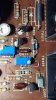
I grabbed a AU222 from that auction site. It's in pristine condition, just some dust inside and all original. Cleaned the dust and squirted the pots with cleaner only. Fired up on a 40 watt dim bulb and no shorts. Plugged a 1k signal in, and left channel had no signal output with loud hiss when headphones connected.
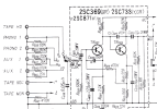
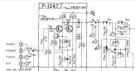
Traced signal with scope and it disappeared at the base of TR8. Checked voltage at base, and was near 10.0. Collector voltage was 9.0 and emitter higher than schematic. I then checked esr on caps and were surprising low. Resisters near tr8 all checked good in circuit. I decided tr8 (2sc871) was shorted, so popped it out.
Checked on pocket tester it showed good, and HFE was 260, a little low. Also checked with dvom and that showed good. I took my best guess and tossed in ksc1845f, and it's up and playing. Voltages are close to schematic.

My question is, the transistor is NG, so how does it test ok? I'm guessing a analog ohm meter might show it shorted.

This little amp sure does lay it on thick and sweet!
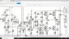
222.jpg
 
Register to hide this ad
Analog or digital, it just depends how much voltage is applied for the tests. As these testers have to account for testing potentially low voltage devices so the voltage applied is low. Unless you have a more sophisticated tester with variable voltage capability.

Of course I may be on the wrong track about why that transistor shows as good when being tested (out of circuit), as opposed to being 'in circuit' and not functioning. :dunno:
 
Last edited:
I grabbed a AU222 from that auction site. It's in pristine condition, just some dust inside and all original. Cleaned the dust and squirted the pots with cleaner only. Fired up on a 40 watt dim bulb and no shorts. Plugged a 1k signal in, and left channel had no signal output with loud hiss when headphones connected.
Traced signal with scope and it disappeared at the base of TR8. Checked voltage at base, and was near 10.0. Collector voltage was 9.0 and emitter higher than schematic. I then checked esr on caps and were surprising low. Resisters near tr8 all checked good in circuit. I decided tr8 (2sc871) was shorted, so popped it out.
Checked on pocket tester it showed good, and HFE was 260, a little low. Also checked with dvom and that showed good. I took my best guess and tossed in ksc1845f, and it's up and playing. Voltages are close to schematic.

My question is, the transistor is NG, so how does it test ok? I'm guessing a analog ohm meter might show it shorted.

This little amp sure does lay it on thick and sweet!

View attachment 2701794

Nice job identifying the failed component. Adding to my knowledge base your experience + @Hyperion comments/exchange. Cool unit. Looking forward to commissioning mine at some point. Are you going to fully restore yours?
 
Last edited:
Nice job identifying the failed component. Adding to my knowledge base your experience + @Hyperion comments/exchange. Cool unit. Looking forward to commissioning mine at some point. Are you going to fully restore yours?
I plan to restore it, but first want to get it playing with the existing caps. Then change them in steps to hear any changes.
I let play for 6 hours and the right channel has a intermittent fuzzy popping sound. Trying to track that down, and learn rather than slam parts at it. Freeze spray on 3 transistors sets it off. Scope on each one and cannot figure which one, or maybe all 3 are guilty. Right side still has a 2sc871 that failed on the left, but freeze spray does not effect it. I sure do enjoy the challenge.
 
Analog or digital, it just depends how much voltage is applied for the tests. As these testers have to account for testing potentially low voltage devices so the voltage applied is low. Unless you have a more sophisticated tester with variable voltage capability.

Of course I may be on the wrong track about why that transistor shows as good when being tested (out of circuit), as opposed to being 'in circuit' and not functioning. :dunno:
My dear old dad still has a Simpson, or maybe it's a Triplet analog. Next visit I plan to rescue it. It has one of the higher voltage batterys, that has been dead since I was a kid in the 60's. I see the battery is still made, or make up a power supply for it.
 
I plan to restore it, but first want to get it playing with the existing caps. Then change them in steps to hear any changes.
I let play for 6 hours and the right channel has anintermittent fuzzy popping sound. Trying to track that down, and learn rather than slam parts at it. Freeze spray on 3 transistors sets it off. Scope on each one and cannot figure which one, or maybe all 3 are guilty. Right side still has a 2sc871 that failed on the left, but freeze spray does not effect it. I sure do enjoy the challenge.

Smart approach. And fun.
 
I finished this one over the past few months. Got it to play without noise by replacing all small signal transistors. It sounded ok but tired.
I planned on working in steps to hear the changes. First thing was to replace the power supply rectifiers with soft recovery ones. To my surprise this alone made an audible change for the better.
Next was the power supply caps. I used nichicon FW series, as the data sheet claims ok for audio power supply. The values were increased, the main cap originally was 1500uf and is now 6800uF, it has a ripple current rating of 3a at 120hZ. The tone board decoupling were doubled in value over the original. Output trans emitter resistors were replaced with 1% non inductive type. Played for a few weeks, but not much change in sound.
I then did the Baxandall mod as per leestereo advice. I noticed an immediate change in the high frequencies, they were distorted and shrill. I then added a .33uF polypropylene cap across the bases of TR805/807 and TR806/808. Mounted these on the trace side. This helped and brought the high freq sound back to normal. This changed the sound alot, it's bright and the bass has more punch.
I saved the output caps for last. The stock values of 1000uf were increased to 6800uf. Leestereo did this on the au555a, and it helps with the low frequency. Nichicon LKS were used here, and this made a noticeable change in bass response.
The phono eq was recapped, but no mods done here.
All switches were disassembled and cleaned, the pots were cleaned with contact cleaner and a dab of F5.

Been playing for a week now, and this little amp simply rocks! The sound is very similar to my rebuilt au555a, the bass seems to have a bit more punch, and it's a tad brighter. Overall it's amazing! Perfect example of less is more.
Special thanks to @Leestereo , for the baxandall advice!

View attachment 2811467 20230213_162241 (1).jpg
 

Attachments

  • 20230213_162331.jpg
    20230213_162331.jpg
    95.6 KB · Views: 81
  • 20230226_103106.jpg
    20230226_103106.jpg
    101.1 KB · Views: 81
  • 20230213_162331.jpg
    20230213_162331.jpg
    95.6 KB · Views: 80
  • 20230226_102859.jpg
    20230226_102859.jpg
    132.7 KB · Views: 82
  • 20230213_162224.jpg
    20230213_162224.jpg
    116.4 KB · Views: 87
  • 20230206_154407.jpg
    20230206_154407.jpg
    101.5 KB · Views: 80
Last edited:
On that hot rodded AU 222, he also mentioned re-wiring the input selector switch circuits. I do notice a SQ difference/improvement when using the tape monitor as a direct input. Would be better to have a direct input without that pre-pre amp circuit.

I'm going to re-configure the AUX inputs and by pass the control amp/phono preamp and associated input resistors R639,641,643,645. That looks pretty basic to do.
One thing I notice is R619 100ohm is in the signal path. Should that be left in circuit ?? Seeing that the signal has to pass through R633 12K ohm, the 100 ohm should have no effect, am I correct with this?
 

Attachments

  • au222 head amp.jpg
    au222 head amp.jpg
    108.5 KB · Views: 20
On that hot rodded AU 222, he also mentioned re-wiring the input selector switch circuits. I do notice a SQ difference/improvement when using the tape monitor as a direct input. Would be better to have a direct input without that pre-pre amp circuit.

I'm going to re-configure the AUX inputs and by pass the control amp/phono preamp and associated input resistors R639,641,643,645. That looks pretty basic to do.
One thing I notice is R619 100ohm is in the signal path. Should that be left in circuit ?? Seeing that the signal has to pass through R633 12K ohm, the 100 ohm should have no effect, am I correct with this?

Sorry I can't help on the technical end. You might consider emailing Frank Speet and maybe offer to compensate him for the use of his design IP.

I posted earlier and deleted, but I'd love to build one of his AU-222 "minimalist" race machines. I have two AU-222. One is mint and deserves a proper factory resurrection but the other is pretty beat up and broken so would be an ideal candidate for the Frank Speet tear down/makeover.
 
Last edited:
"The AU222, like the 555, has a peculiar input circuitry, where all inputs, including the line inputs, pass through the phono preamplifier! For the aux inputs the signal is first reduced tenfold, than amplified again. The RIAA correction circuit of the phono preamp is set to neutral. With modern high level signal sources such as D/A converters and CD players, this can result in driving the phono preamp into distortion, which cannot be corrected with the volume control! When I minimalise an amplifier like this, I connect the Phono 1 input directly to the actual phono preamp input and re-wire the source selector switch to select at line level, thus making all the other inputs, including Phono 2 and Tape Head, line level and routing them directly to the volume control instead of through the phono preamp first. A revelation soundwise and for modern applications a much more usable amplifier."

This was interesting - the factory config pushes all inputs through the phono/RIAA correction. This does seem odd (if you are running an input other than vinyl) - wonder what that curve looks like?

He mentions the AU-555 having the same config but not the AU-555a. I haven't looked at the schematic, yet, but his omission must mean Sansui separated the other inputs from the phono section on the AU-555a?

Did you make a similar input mod to your AU-222, @Scott Muni?

Edit: Looks like the AU-555a does not run the other inputs through the phono.

AU-222
Screen Shot 2023-08-14 at 9.16.16 PM.png

AU-555

Screen Shot 2023-08-14 at 9.16.30 PM.png


AU-555a
Screen Shot 2023-08-14 at 9.16.46 PM.png
 
Last edited:
I have to wonder about the decision to pass all sources through the preamp phono circuit. It was not done with the earlier AU-111, nor the near current AU-777 or AU-777a, and I doubt the AU-999 although I have not looked. I wonder if the selector switch used for the cheaper AU units of that era was a simpler single level design which they wanted to use for cost savings. Whereas the switches in the high level amps were double layer (?). I am guessing the later 555a indicates the compromise needed to be fixed. The AUX sources should not be correct for the RIAA curve. And my untrained eye cannot see how the RIAA correction circuit is "set to neutral" on the 222 schematic.
 
I wrote to Frank Speet, about my plans to have aux to have direct input. Waiting for a response. Not sure about R619 and the value of R645/641.

The input switch on the au222 is a double layer, so cost does not seem to be a factor. Definitely odd they did this. Maybe some of the equipment back then had a lower output level, and needed more gain??

There is a difference in sound when the inputs are compared between aux and tape monitor. I usually have the DAC input to tape, and tuner to aux, so was not too concerned about this, but now that Jim got my OCD working.....
 
And my untrained eye cannot see how the RIAA correction circuit is "set to neutral" on the 222 schematic.

For my knowledge, what are you looking for in the schematic that shows a neutral RIAA correction?

A little off topic from the AU-222, but along the lines of RIAA, this thread by @Leestereo was a revelation for me understanding RIAA and how the pros like him manage the RIAA correction. And after thinking about this "all AU-222 inputs through the phono stage" I'm pretty sure Ben mentioned this to me about the AU-222 at one point when discussing the first generation Sansui integrated's - it went over my head at the time - seeing it now with a bit more experience I understand what he was explaining.

 
Last edited:
Back
Top Bottom