• The move to the new server is done. There are some software and database maintenance updates in process. This has us passing the hat around to help out. We appreciate any donations. Seriously, even a dollar helps. The payment page may be found here - https://www.audiokarma.org/support.html

New amp project AU 222

I wrote to Frank Speet, about my plans to have aux to have direct input. Waiting for a response. Not sure about R619 and the value of R645/641.

The input switch on the au222 is a double layer, so cost does not seem to be a factor. Definitely odd they did this. Maybe some of the equipment back then had a lower output level, and needed more gain??

There is a difference in sound when the inputs are compared between aux and tape monitor. I usually have the DAC input to tape, and tuner to aux, so was not too concerned about this, but now that Jim got my OCD working.....

Anxious to hear back from you/Fank.
 
On the AU-222, Tape Head seems to go through the preamp phono correction but without initial signal reduction, whereas Tape Monitor bypasses the Phono Eq circuit but has some modification (R647). I am seeing Tape Head on these selectors (AU-222 and AU-555) for the first time. I would guess there is a difference between the sound of these two paths. Was Tape Head designed to monitor the audio signal coming to the tape head during recording? (As in 3 head tape decks.) Or from the audio coming from the playback head reading the tape? With the potential of Tape HD feeding directly into Tape Rec, was this a potential screaming feedback loop or at least an echo loop?
 
Last edited:
On the AU-222, Tape Head seems to go through the preamp phono correction but without initial signal reduction, whereas Tape Monitor bypasses the Phono Eq circuit but has some modification (R647). I am seeing Tape Head on these selectors (AU-222 and AU-555) for the first time. I would guess there is a difference between the sound of these two paths. Was Tape Head designed to monitor the audio signal coming to the tape head during recording? (As in 3 head tape decks.) Or from the audio coming from the playback head reading the tape? With the potential of Tape HD feeding directly into Tape Rec, was this a potential screaming feedback loop or at least an echo loop?
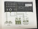
The owners manual says the tape head input is used for 7.5 tape machines, no clue what those were.
 
7.5 meaning reel to reel using 7.5" Inches per second speed. But even at 3.75" or 15" IPS, speed should not matter.
And if they meant reel size, again, does not matter.
 
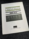
To add some context. Just unearthed the manual for the other thread. Such a cool piece of Sansui gear :).

IMG_0378.JPGIMG_0382.JPGIMG_0383.JPGIMG_0384.JPG
 
Tape head is a direct feed from the head of certain old tape decks, and bypassed regular preamp circuits, using NAB equalization, AFAIK.

I was once looking into that as my Fisher 400 has a tape head input. There is more info here on AK about it:

 
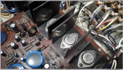
What are the spec on your output transistors? Frank Speet went with the 2SC1111 on his build. Mine (original) are 2SD247.

Frank's (just noticed he left the OG trim pots in)
Screen Shot 2023-08-17 at 5.42.40 PM.png

My factory originals
IMG_0462.JPG
 
Last edited:
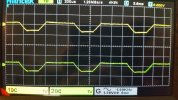
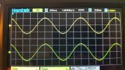
I have the au222 on the bench, with the scope connected before I mod the AUX inputs.
Real easy to overdrive the AUX into clipping the phono amp. Same input voltage, the non clipped is the tape loop. Other than that I don't detect much.
 

Attachments

  • 2222 aux input.jpg
    2222 aux input.jpg
    108.5 KB · Views: 5
  • 222 tape in.jpg
    222 tape in.jpg
    102.9 KB · Views: 5
I finished this one over the past few months. Got it to play without noise by replacing all small signal transistors. It sounded ok but tired.
I planned on working in steps to hear the changes. First thing was to replace the power supply rectifiers with soft recovery ones. To my surprise this alone made an audible change for the better.
Next was the power supply caps. I used nichicon FW series, as the data sheet claims ok for audio power supply. The values were increased, the main cap originally was 1500uf and is now 6800uF, it has a ripple current rating of 3a at 120hZ. The tone board decoupling were doubled in value over the original. Output trans emitter resistors were replaced with 1% non inductive type. Played for a few weeks, but not much change in sound.
I then did the Baxandall mod as per leestereo advice. I noticed an immediate change in the high frequencies, they were distorted and shrill. I then added a .33uF polypropylene cap across the bases of TR805/807 and TR806/808. Mounted these on the trace side. This helped and brought the high freq sound back to normal. This changed the sound alot, it's bright and the bass has more punch.
I saved the output caps for last. The stock values of 1000uf were increased to 6800uf. Leestereo did this on the au555a, and it helps with the low frequency. Nichicon LKS were used here, and this made a noticeable change in bass response.
The phono eq was recapped, but no mods done here.
All switches were disassembled and cleaned, the pots were cleaned with contact cleaner and a dab of F5.

Been playing for a week now, and this little amp simply rocks! The sound is very similar to my rebuilt au555a, the bass seems to have a bit more punch, and it's a tad brighter. Overall it's amazing! Perfect example of less is more.
Special thanks to @Leestereo , for the baxandall advice!

View attachment 2811467 View attachment 2811469

Hey Scott, I'm trying to decide on my output and filter cap sizes, came across this thread.

What are you calling the tone board decoupling caps? Do you mean the ones on the phono board = c605?

Or maybe the one on the rail in the power amp section c821?
 
Ohh okay the caps that supply the rails. Yup I'm doing the same, doubled values. Except 6800 for the filter and 3300 for the outputs. I think I've done one other one with 6800/4700. I think you did the same or similar values. Going to change out the rectifier diodes as well and put RC snubbers on em. Probably unnecessary...
 
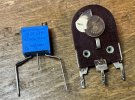
@Scott Muni what value trimmer did you go with here? I can't read it from the photo. And the way you solved the trimmer pinout is very cool. The original VR804/803 pinout footprint is huge and I was wondering how to deal with this using a Bourns multi-turn. Great photo. Thanks.

View attachment 3841708
I used these Bourns trimmers when I restored an AU-222:

Screenshot 2026-09-23 at 5.02.18 AM.png

For the bias pots, given the wide spacing of the legs, I soldered on "leg extensions" from capacitor cutoffs. Worked well.

IMG_0385.jpegIMG_0386.jpeg

For the output pots, the legs can be bent out to fit leaving just enough for the solder pad.

IMG_0387.jpeg

All replacements worked fine.

IMG_0389.jpeg
 
Back
Top Bottom