• The move to the new server is done. There are some software and database maintenance updates in process. This has us passing the hat around to help out. We appreciate any donations. Seriously, even a dollar helps. The payment page may be found here - https://www.audiokarma.org/support.html

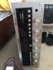
New to me Marantz 2275 (with issues)

xalara76

Active Member
Hey Y’all. Picked up a beautiful Marantz 2275 with some issues :( but I can’t complain. Anyways lets get this puppy fixed ! So far there is no output from AM/FM (like non at all not even static) in either channel ! Tried aux with my phone and after deoxiting the unit very well and cleaning relay too I got the Left channel to play nicely but there is zero output from the right channel still.. Plugged rca to 3.5mm into main in with my iphone and problem persisted (no right channel). So im lead to believe the right amp board has issues. (It also gets quite warm which makes me think bad output transistors. Someone definitely was in here before and did some sloppy work. While testing in AC J806 on PS board for current going to TUNER section I got a blank screen on my multimeter and some lovely magic smoke came from the PS board as well ( bad caps im assuming.) What else should I check ? Im ordering a amp and power supply recap kit as well as new output transistors. I just dont know where else to start ?
 
Register to hide this ad
The 13.4V at J806 should be DC. What are your ECB voltages at H804? If you have a bad amp board, unplug it before testing if you think something is shorted. Or better yet, use a Dim Bulb Tester.
 
Or better yet, use a Dim Bulb Tester.

Yes that!!!

I am not that familiar with that model and I hope someone who is chimes in soon. But....

Go to HIFI Engine and download a manual. Go through the manual correction thread (its a sticky near the top of the Marantz forum) and note corrections.

Sounds to me you have power issues to attend to before recapping. Always fix your issues before diving into a mad cap attack(this will save you the unneeded headaches.) I would start lifting some legs on the power supply checking transistors and resistors because something threw that some out. Get your power supply 100% even if you must disconnect the loads then work your way out. Recap one board at a time then listen to the results and if you make a mistake it will be easier to find. I may be wrong here so I hope others do chime in and give them time cause they will.

Like Steven said. Don't apply power again until you build yourself a dim bulb tester. You tube has several examples.

Be patient! It took me about 6 months to get my first receiver up to 100%.
 
The 13.4V at J806 should be DC. What are your ECB voltages at H804? If you have a bad amp board, unplug it before testing if you think something is shorted. Or better yet, use a Dim Bulb Tester.

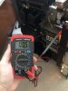
Hey guys ! Tested at J806 on the multimeter in DC. I think I have my multimeter set to the right spot.. showing 0.00 ? Guessing its dead ? Where too next ?
 
Yes that!!!

I am not that familiar with that model and I hope someone who is chimes in soon. But....

Go to HIFI Engine and download a manual. Go through the manual correction thread (its a sticky near the top of the Marantz forum) and note corrections.

Sounds to me you have power issues to attend to before recapping. Always fix your issues before diving into a mad cap attack(this will save you the unneeded headaches.) I would start lifting some legs on the power supply checking transistors and resistors because something threw that some out. Get your power supply 100% even if you must disconnect the loads then work your way out. Recap one board at a time then listen to the results and if you make a mistake it will be easier to find. I may be wrong here so I hope others do chime in and give them time cause they will.

Like Steven said. Don't apply power again until you build yourself a dim bulb tester. You tube has several examples.

Be patient! It took me about 6 months to get my first receiver up to 100%.

Hey guys ! Tested at J806 on the multimeter in DC. I think I have my multimeter set to the right spot.. showing 0.00 ? Guessing its dead ? Where too next ?
 
Hey guys ! Tested at J806 on the multimeter in DC. I think I have my multimeter set to the right spot.. showing 0.00 ? Guessing its dead ? Where too next ?

got it to show 0.05 at a point then it went to 0.00 again.
 

Attachments

  • 4C45FB75-A051-4305-A0AC-F0166B5673DD.jpeg
    4C45FB75-A051-4305-A0AC-F0166B5673DD.jpeg
    95.7 KB · Views: 28
got it to show 0.05 at a point then it went to 0.00 again.
Whatever smoked is obviously not letting voltage pass through. At least your meter is on DC now checking DC, not AC. :p You could have slipped a probe that caused the smoke to fly. It is very easy to do. (been there, done that) Replace whatever smoked and use a DBT before you check it afterwards. Hopefully it is just that smoked resistor I see in the photo.
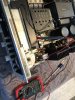
 
Whatever smoked is obviously not letting voltage pass through. At least your meter is on DC now checking DC, not AC. :p You could have slipped a probe that caused the smoke to fly. It is very easy to do. (been there, done that) Replace whatever smoked and use a DBT before you check it afterwards. Hopefully it is just that smoked resistor I see in the photo.


Power supply fully recapped with a kit I had purchased on eBay. Seems to have brought life back to the unit. I now have a.m. in both channels when headphones are placed into dub out jack, FM is just static all across and only plays in the left channel. I will recap amp board tomorrow and report back. Anything else I should check for? Also bought new transistors ! MJ15003 & MJ15004
 
where should I check voltages on PS ? I set the dc offset to 35V as stated in the SM
The 35V is not the DC Offset. That is the power supply output voltage. DC Offset is measured at the speaker terminals once you get the amps working properly. The other important power supply voltage is 13.4V DC at J806. That powers the tuners and other boards.
 
The 35V is not the DC Offset. That is the power supply output voltage. DC Offset is measured at the speaker terminals once you get the amps working properly. The other important power supply voltage is 13.4V DC at J806. That powers the tuners and other boards.
Gotcha, so i’ll attach negative lead to the TT chassis ground then positive lead to J806 and you’re saying it should read 13.4V DC ? I will report back shortly with values
 
The 35V is not the DC Offset. That is the power supply output voltage. DC Offset is measured at the speaker terminals once you get the amps working properly. The other important power supply voltage is 13.4V DC at J806. That powers the tuners and other boards.
Got back with the results at J806. Im getting 12.86V DC.. hmm not terrible but where do I go next to get it up to 13.4 ?
 

Attachments

  • D3C70382-0E82-4B4D-82EA-A9BC39121EF7.jpeg
    D3C70382-0E82-4B4D-82EA-A9BC39121EF7.jpeg
    147.4 KB · Views: 16
Got back with the results at J806. Im getting 12.86V DC.. hmm not terrible but where do I go next to get it up to 13.4 ?
Are you on a dim bulb tester? That could account for the difference. But basically, 0.5V shouldn't affect the function of anything. I would keep moving forward with your restoration. Just test, test, test after everything you do, preferably with a DBT.
 
Back
Top Bottom