• The move to the new server is done. There are some software and database maintenance updates in process. This has us passing the hat around to help out. We appreciate any donations. Seriously, even a dollar helps. The payment page may be found here - https://www.audiokarma.org/support.html

Next Yamaha PX3 linear TT on Audiokarma - restoration (problems with photo elements solved)

Martynka

Well-Known Member
Hi,

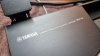
One year ago I bought PX3.
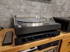
20220121_223732.jpg

20221028_232746.jpg

Nice looking... and it was everything what I say positive. Ok, another positive all legs in excellent condition.

20221028_232932.jpg

Cartridge was worn, but original Yamaha MC5.
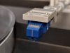
20220308_123752.jpg

I gave it to my friend and he changed it to shibata on boron. At this time it is the best sounding TT I ever have.

Now time for problems:

1) Not working buttons. Only DOWN and CUT sometimes works. I push by hand arm over track and push DOWN to play.

I solved this problem. Opened Yamaha
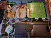
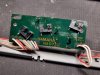
20221028_234544.jpg

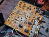
remove main PCB

20221028_235243.jpg

When PX-3 was open I check all value of dapacitors and ordered all. I will change it.

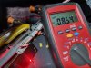
I checked one more time switches with multimeter...
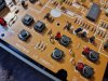
20221029_000023.jpg

and not warking. I use contact spray and checked one more time
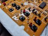
20221029_000516.jpg

works fine but problem with this square ( LEFT and RIGH arm control ) I clean it one more time, this time I put more cleaner via little hole and start working.

It was the easiest job with PX3.
 
Register to hide this ad
2) problem with moving arm:

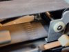
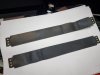
After opening Yamaha, I checked belt. Was full of dust and with traces of drive wheel.


20221030_215035.jpg

20221030_220850.jpg

When tried to move arm drive wheel rotate but belt no moves. I dissasembly all system:

20221030_222410.jpg

20221030_222155.jpg

20221030_224916.jpg

and clean

20221030_231435.jpg

20221030_234251.jpg

20221030_225800(0).jpg

I assembly clean belt but up side to the down and begining goes to the end

20221031_002830.jpg

20221031_002811.jpg

and... It's alive !!!

Works even up:


both speed:


and follow arm

 
3) Automatic - here I need help:

Drive working, buttons working, but if I push 17 arm goes down and stay in place. When I push 30 always goes to the start position and stop. At end of the vinyl rotate still, I need push CUT to finish and back arm to start position.

I checked:

- LEFT end position switch by multimeter and stop motor when push
- RIGHT end position switch by multimeterand stop motor when push
- 7 pin connector +12V on PIN 6
- 7 pin connector 0V ( GND ) on PIN 2
- 7 pin connector on +6V for LED on PIN 7
- 7 pin connector on 3, 4, 5 PINs still abut 11V even when slide arm and hide photo receiver.

all LED emits red light.

20221030_222304.jpg

but not change voltage when slide arm.

I noticed that if I give more light on photo reciver ( from lamp ) voltage on PINs 3, 4, 5 drop few volts. It means for me, that we have HIGH LEVEL about 11 V ( the same like 12 V supply but via resistors ) and LOW LEVEL when lights goes to the photo reciver.
Do I think right ??

If right, it means for me that I have not enought light from LED's to give LOW LEVEL and for system still all leds are hide.
Do I think right ??
 
Last edited:
Martynka, that is great work amigo!

Question 1) You mentioned replacing the caps, had you done that before you cleaned the switches or did cleaning the switches alone solve the problem?

Question 2) What did you use to clean the belts with?
2b) What kind of cleaner did you use for the switches, Deoxit 5?

I have one of these in my "B" system and it works, most of the time, and sometimes it just won't respond when I push the "30" button but I can still use the button to move the arm to the left and the "Down" button still works, so it's a bit of inconvenience but manageable.

NOTE: When I haven't used the PX-3 for some time, maybe a couple weeks, it is likely to work the first time I try the 30 button but after that, it will likely not work.

PS - If I use the thing every day for a while, it seems everything starts to work as it should.....I think it's trying to tell me something!!!

Many have fiddled with these decks, most have concluded that a re-cap is necessary or even messing with the LED sensors, a trickier proposition. I've been fortunate with mine that while I have had to re-adjust the position of the sensors from time to time, they are still working.

Again, excellent work and thanks for posting this!
 
Last edited:
I measure one more time all photo elements. All works the same that I thing that it is not a problem with broken one but with all system.

Here is graph from my multimeter:

Screenshot_20221031_180417.jpg

When system started and internal led light on photo receiver I have about 10,8V, when arm moved and hide by rail led, and photo reciver is without led light I have about 11,8V. It is only 1V drop. Not enough to change HIGH level to LOW level.

If I use external light to photo receiver voltage can drop to 0,8V. It should be ok to change HIGH to LOW.

maybe with notes on graph will be better

Screenshot_20221031_180417b.jpg


And questions:

Do you know how big should be drop to change H to L ?? to 6V or low ??
Why if all receiver react the samo on external light not work with all leds ??

Maybe someone has the same problem ??
 
You mentioned replacing the caps, had you done that before you cleaned the switches or did cleaning the switches alone solve the problem?

No, I have still old caps. New are on the way and will be change after pick up.

What kind of cleaner did you use for the switches, Deoxit 5

I use cleaners from Poland.

First:
https://termopasty.pl/en/produkty/kontakt-pr-3/

and
https://termopasty.pl/en/produkty/kontakt-s-3/

and after few minutes clean all dirt with :
https://termopasty.pl/en/produkty/kontakt-u-3/

What did you use to clean the belts with?

Brush with soap and water. After wash use scotchbrite and clean with https://termopasty.pl/en/produkty/kontakt-ipa-plus-2/

but after wash with water and soap looks the same, like new.
 
Thank you for your explanations! Best of luck with the photo interrupters, those can be a pain I'm told. Did you know that there's a guy, Professor Bizzt I believe is his handle, that fixes these things and has a ton of information about them. Last I heard, he had a store on the web.

Here's his contact information:

https://www.webstore.com/store,pgr,225332,user_id,shop
 
Best of luck with the photo interrupters, those can be a pain I'm told. Did you know that there's a guy, Professor Bizzt I believe is his handle, that fixes these things and has a ton of information about them. Last I heard, he had a store on the web.

I saw it. 150 USD for few LED o_O . I know, knowledge costs money. I will try to solve it by myself.
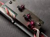
Schematic shows that voltage should drop about 1V. I have it only if put more light from external source.

LED are connected in series with resistor R37 680R, on this resistor Voltage drop 6V. I check with 470R, 220R, 100R, 56R and still have not enough drop voltage on reciver with internal LED. The same will be if I remove one extra LED ( for 10 size ). I afraid that rest LED's can be burn.

I will remove one more time tonearm with belts and remove PCB with sensors. Check conections and if everything will be ok... remove LED with new one.
 
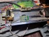
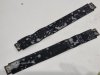
OK... I removed tonearm, belts and sensors PCB

20221031_220038.jpg

desoldered led/receiver sets

20221031_222340.jpg

Yelow dot is LED side

20221031_222636.jpg

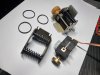
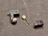
and open and remove LED

20221031_230606.jpg

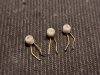
tres amigos

20221031_230726.jpg

I think, now I solder rest of plastic housing with sensor back to PCB and will try to find proper new LED.
 
You are very fortunate to have the ability to do such things on your own.....that's very impressive amigo! I have frequently heard that replacing all the caps on the board will fix most/many problems so you might delay moving forward until you have finished that. Then see what you have. In any case, I really like my PX-3 and use it more often than the Thorens or the Dual I have in that system.
 
...so you might delay moving forward until you have finished that.

if after recap I will have to much light it will be not a problem, I only change R37 resistor to drop more voltage.

Now I checked with another led and I have 0,8V !!! It should work !!! I back to work :)
 
Good work Martynka!

Thanks,

and now... Ladies and Gentlemen, Damen und Herren, Mesdames et Messieurs....

17:


30:


If I was know that repair takes few hour, I done it one year ago :)

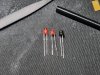
I took 3 red LED ( red because works with 2,1V it means full power with this 6V supply ), I cut them with a file and put it to heat shrink tubing.

From left: new one , shortened, with tube

20221101_003307.jpg

after install looks like from here :) and give brighter light

20221101_010428.jpg

20221101_010349 1.jpg

20221101_010650.jpg

20221101_010658.jpg

and now when tone arm moving I have only two measurment on multimeter: 10,83 V or 0,83 V

Screenshot_20221101-012640_e-Bull .jpg

yes, yes, yes, bravo me !!!

Tomorow I put all parts together and check with vinyl. Now in Poland is middle of the night.
 
I assembled all the parts at night (couldn't sleep, too much excitement with the PX3 working), and after few hours sleep I started with regulations.

First mechanical adjustment: tonearm balance, tracking force, tonearm height.

After that electrical adj. On instruction we have test pin on main PCB to measure mV for correct following adjustments. On the same PCB we have VR1 to adjust in UP position. It will be stupid to must dissasembly PX-3 for adjust and measure. I can't find it in instruction but under metal plate i plug.

20221101_102811.jpg

my curiosity told me to open it up and... BINGO !

20221101_102716.jpg

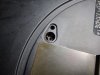
inside bigger hole is test pin ( looks like RCA but I put + from multimeter inside and - touch outside ), inside smaller hole is VR1 to adjust.

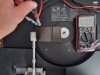
In up position on the middle of mechanical center I have correct measurement, about 4 mV ( should be 0 V + / - 50mV )

20221101_092657.jpg

but can be better :)

20221101_100905.jpg

Next regulation with DOWN position 7 mm over TT surface and... ups

20221101_102042.jpg

regulation with VR4 ( blue variable resistor on tonearm PCB

20221101_104018.jpg

give me fully acceptable

20221101_102316.jpg

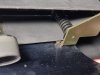
On the end I need regulation of point where tonearm drop down. After all dissasemble and claening this poin was to early but I adjust it with eccentric bolt ( this plastic black, on bottom circled in red - first must be losen metal bolt, one on left near plastic, second on right end of metal frame )

20221101_100409.jpg

Now time to listening music and check work in practice.
 
Great work

Great job

Thank you.

You have more patience than I do by far.

I had nothing to lose. PX-3 was not working like should, I couldn't break it more :)

Really, if I knew it was that simple, I would have done it right after purchasing the PX-3.

Biggest problems was with automatic works. I was tired of searching for information on how to do this and how it works. That's why I started with measurements and guesswork until it came together.

If something is difficult to understand here, please feel free to ask, I will be happy to help.
 
I have been following this from the beginning and am really excited with/for you Martynka! It's clear that you have a good working knowledge of electronics and that was a big help.

Can you tell me where you sourced all the electronics that you plan to replace/renew? Capacitors, resistors etc. etc. If you have a list of everything that one needs, I would sure like that as I'm going to try to do this with my table before too long. I am the original owner of my PX-3, bought it through the PX in Germany back in 1983 or 82, can't remember. In any case, if you have that information it would help to motivate me! Or, better yet, come on over here and take a vacation so we can do it together!!! Have fun listening amigo.....
 
Back
Top Bottom