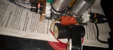
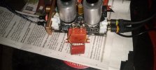
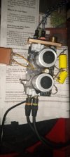
Swapped the 20uf cap today for a 2.7uf and it now seems to have more treble and less bass; less boomie and more fizzy. Initially added 2.7 to the 20. Might try 1 and .047. Still experimenting. Listening. Trying to squeeze out treble to my liking. without an oscope ,hard to prove. Might be becoming accustomed to the sound.
Okay! At 1uf the sound has more treble. Not there yet, though. Tried .47 and the amount of hiss was unbearable, unstable, while playing miles davis' flamenco sketches. Currently at .68uf. much better now.
Looks like the cap you’re messing with was originally the electrolytic that’s marked as C14 on the board, correct?
If so, that one seems to be in the power supply, not in the audio portion of the circuit. If it was in the audio portion of the circuit, there would be two of them with identical specs, one for each channel.
Caps in the power supply are used to filter out noise.
That’s why you got hiss when you changed the value. If the change in value was actually boosting the treble from your source, that would indicate that the hiss was also coming from the source. So either the recording contains a high level of hiss or the source component is extremely noisy. Both situations seem unlikely unless the hiss is also present when listening without the preamp.
Replacing an electrolytic, especially a cheap one whose quality may be questionable, with a film cap may yield some audible improvement but it’s best not to change the values of components when you don’t know what part of the circuit they’re in or what role they play.
The power supply in the E6 takes a 5v DC input and boosts it to 105v.
According to the blog that Lenco followed when replacing the four 1uf 250v gray caps (Doctorjohn Cheaptubeaudio), the boost circuit is a switch mode supply. The blogger, who has since passed away (RIP), asked but the manufacturer would not supply a schematic. I don’t know the technical details of how the voltage boost is accomplished, but I do know that switch mode supplies have high frequency switching noise which must be filtered out.
A commonly used element in a power supply consists of a series resistor followed by a cap to ground. This configuration forms a low pass filter. The rolloff point created by the filter allows anything below the rolloff frequency to pass and filters out the high frequency noise above the rolloff point. It’s not a hard cutoff, it’s -3db at the rolloff point then it drops gradually.
In such a filter, if the value of the cap is lowered the rolloff point goes up. This would allow more of the high frequency noise that’s generated by the boost circuit into the supply voltage for the tubes. That’s why you get a lot of hiss. If the hiss is not part of the recorded audio signal then it’s not coming into the preamp via the inputs. It’s noise from the power supply.
If you want more treble, it’s the high frequencies in the
audio signal that you want to boost, not power supply noise. Just use an EQ of some sort between the source and the preamp. An EQ boosts or reduces the strength of the various frequencies that are actually present in the audio signal.
From the pics I’ve seen there are four electrolytic caps. The two in the middle are not the same size so I assume their values are different. Those are the ones in the power supply boost circuit.
The two smaller ones, which seem to be the same size, are located towards the ends of the board. Those would be the cathode bypass caps which are part of the audio portion of the circuit. If I’m correct, you’ll find that they are the same value and voltage. Value will typically be relatively high and voltage will probably be relatively low compared to the caps in the power supply. You can use the continuity function of your meter to confirm their role. The + of each cap should connect to either Pin 1 or Pin 8 of the nearby tube.
If your treble is rolled off it’s more likely due to the PIO caps, which are typically not as bright as film caps. Two of the original gray caps are input caps and two are output caps. Again, one per channel using the same values. According to the blog, the ones labelled C2 and C3 are input caps and the ones labelled C1 and C15 are output caps.
The purpose of an input cap is to block any potential DC that might be on the output of your source. Most sources already have DC blocking caps on their output. If there is no DC, and there shouldn’t be, then there’s nothing to block and you could just remove the input caps and replace them with a wire.
I’ve never actually come across a source that outputs DC that needs blocking. There would likely be hum if there was any. That’s why my most recent preamp build, which I linked above, does not use blocking caps on the input.
The other two (C1 and C15) are output caps which block the DC voltage on the tube’s plate from the output that goes to the amp. You measured 65v on the plate previously so one lead of each cap should have 65v on it and the other lead should have 0v DC. The cap in series with the signal followed by a resistor to ground form a high pass filter.
If you use the resistance function on your meter and measure (with unit off) between the 0v lead (or the center of the output RCA) to a ground you can determine the value of the resistor. Then we can calculate the -3db high pass rolloff point of the audio signal at the output.
As has been pointed out, both by me and on that blog, with these little commercial preamps you’re limited to upgrading the quality of a few caps. It’s kind of like wanting to make your car faster but the only thing you’re allowed to change is the tires.
That’s why I keep suggesting that people who are into modding take the next step and try DIY. This gives you total control over the entire circuit, not just the “tires”. Preamp circuits like this are as simple as it gets. Breadboard . . . experiment . . . build!