• The move to the new server is done. There are some software and database maintenance updates in process. This has us passing the hat around to help out. We appreciate any donations. Seriously, even a dollar helps. The payment page may be found here - https://www.audiokarma.org/support.html

Oh no, Sony TA-1120

Frank Solem

New Member
Hi
Felt like the luckiest guy on the planet, got hold of a very nice TA-1120, the original without the headphone jack. With a original, also nice wooden box and pristine faceplate.
I guess it has been a problemchild, since the power amp was bypassed, and previous owner tried to use it as a pre. I bought it as a none working unit.

I have reversed previous job, so its back to original now.
Replaced all ecaps and 2sc401 trans. Pulled the rest of the transistors and checked them OK. The problem now is my silly brain I guess. I get crazy voltage readings. C505 has 40v on + (should be 23v), but also 33v from - on same cap to ground.
I have been re-checking the transistors, checked resistors and diodes all over. But I just dont understand. I would guess it had to be a ground issue, but it seems to be OK.

It reacts quite normal when i hook it up to my DBT and the relay clicks in after 5-6 seconds.
The power on the main cap is low, but im guessing that is partially DBT and partially related to the other voltage problem. Main cap voltage sits around 70V.
All output transistors have the correct voltage range compared to the main voltage, except the pair to the very left. They are 10v to low. The rest is 70V and 35V.

Edit, just remembered, there was a open diode in the rectifier bridge when I got it. I changed all four.
I have checked the trafo, it delivers 240V.

Advice is gratefully received
Pictures can be posted
 
Register to hide this ad
I'm not sure I understand C510. I'm starting to think that is a big part of the problem. There is a ground point next to the left power amp board.
I have placed a 0,047uf filmcap from GND on the left power amp board to the ground nut on the chassis.
But what is the other C510 in the schematics? 0,0047uf from GND on right power amp board to R523? Where is this to be found?
 
Hello. C505 negative terminal should be connected to ground, so if you are measuring +33V from ground to C505 negative pin, your ground connection is not OK, or you are taking the reference for your readings in the wrong point.

C510 at the power supply (bottom left of the schematic, beside the diode bridge) is simply a by-pass capacitor in parallel to C508 4000uF. Schematic says 0.0047uF but the parts list says 0.047uF Mylar capacitor.

Please try to identify the parts on the schematic, and try to indentify them in the PCB, so I can understand better your problem. When you write "All output transistors have the correct voltage range compared to the main voltage, except the pair to the very left.", I can't know which transistors are at the very left.

Apart of that, can you adjunt the Bias in both channels, and play music with the amp?
 
Last edited:
Thank you sir and sorry for my clumsy description. I can see now that i have indeed taken my readings in the wrong point. I used negative on C508 as groundpoint. I see now, that is wrong.
''Left outputs'' must be X217/218. They are lower on the connector than the what is supposed to be.
I will have a closer look at the schematics and have another go.
I havent come to bias yet. I guess I could set the correct bias on right side, not the left. I have checked all the pot's.
Thanks again and I'll be back shortly.
 
I have fixed some amps/receivers the last 3 years, but Im by far a professional. I think i have fifty some units now :)
Have to admit to not undestanding this one quite.
Here are some measurements made from the ground point on the chassis:

So sorry, I have lots of space on the original, but i cannot seem to save it when posting
C, B, E comes under each transistor
Please see the attached file.

X119 X219 X115 X215
C 24v C 26v C 22,7v C 24,7v
B 0,5v B -6,8v B 0,9v B -6,2
E 0,0v E -7,3v E 0,6v E - 6,5

X1117 X217 X116 X216
C 24v C 26v C -32 C -33
B 0,6v B -6,9v B -0,3 B -7,0
E 0,0v E -7,4 E -0,3 E -6,7

X120 X220 X114 X214
C 0 C -7,5 C 0 -7,9
B32,0 B -33,7 B -40 -31,6
E33,8 E 33,8 E-33 E -35


X118 X218
C 0 C -7,5v
B 32v B -33,4v
E 33,8v E -33,9v


Here whats fooled me, measurements from - on C508 to collector on each output transistor now:

X119 86v
X120 43V
X118 86V
X117 43V

X219 64V
X220 29V
X118 64V
X117 29V

I really dont understand this. Please point me in the right direction.

I can also feel some voltage in the chassis, when my underarm touches the chassis where the skin is thinnest.
 

Attachments

Last edited:
On the 1120a the +B rail is 83v and the centre voltage is 42.3v. I haven't looked at the earlier model schematic but it looks close to your x117-120 side.
 
Thank you sir and sorry for my clumsy description. I can see now that i have indeed taken my readings in the wrong point. I used negative on C508 as groundpoint. I see now, that is wrong.
''Left outputs'' must be X217/218. They are lower on the connector than the what is supposed to be.
I will have a closer look at the schematics and have another go.
I havent come to bias yet. I guess I could set the correct bias on right side, not the left. I have checked all the pot's.
Thanks again and I'll be back shortly.

C508 (4000uF 100V) is the negative of the main filter capacitor. That's the correct reference point for your measurements. If you are getting different voltages from other ground points, check the continuity between the different ground points shown in the schematic and C508 ground. Perhaps your problem is a broken ground connection.

Another thing I see, a "healthy" transistor should have approx 0.6V from Base to Emitter. And I see that condition is not met by some of your transistors. X116 shows the same voltage at B and E, it looks like shorted from B to E. And X114 measures 7V, looks like it's not OK or R112 open.

Output transistors, TR217 and 219, and TR117 and 119 should be all physically connected directly to C508 positive, so voltage at all those points should be the same. They must be electrically connected, no measurable resistance between all of them to C508 positive.

TR 218, 220, and 118 120 should have approx 43V at the collectors, and a few mV (manual calls for 25mV) at the emitters.
 
Thanks again! I will pull some transistors and measure again. Maybe change them in case of some are weak, but not broken.

I just dont understand the grounding of this unit. Is all ground from power amp boards to chassis going through C510? On mine it is.
So when i measure from gnd on any of the power amp boards to chassis ground, i get around 2000 ohm. Im used to that being 0 ohm. Same from - on C508 to chassis ground, 2000 ohm.

can I replace C510 with a cable? I feel so silly now...
 
Last edited:
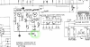
There could be one capacitor from the audio ground to chassis, but the power amp boards should be all connected to C508 ground, and that ground connected to chassis at just one point. The schematic shows that point at Diode 10 or C505/506 . So, the chassis should have continuity to C508 negative terminal and to the rest of the circuit ground. Check that "G" connection shown in the schematic. It must be connected to the rest of the ground, including C508 and the diode bridge rectifier. That "G" appears at several ground points on the schematic. All of them should be interconnected.


sony-ta1120-ground.png
 
BTW, NEVER ever think about jumping a capacitor with a wire. A capacitor is an OPEN CIRCUIT to DC voltage. when the unit is at Idle, without any signal present, just DC on the circuits, the capacitor is like an open circuit. If you jump a capacitor, you can create a short circuit and damage things.
 
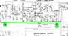
Here you can see C510 connected to chassis, but also the circuit ground connected to point G (which should be connected to the other G shown in my previous post, connected to chassis)

sony-ta1120-ground_II.png
 
Thanks, I feel more optimistic than for a long time :) I was really lost, but I think you might have steered me in the right direction.
I changed the ground cable you are referring to earlier today, the original looked corroded and were short. But then it makes sense with 2K ohm between - on C508 and chassis. I'm measuring through R523(680 ohm) and whatever is the smallest resistanse to ground after that.

I will work on and come back with a conclusion :)
 
First of all, thank you for your insight and support Elnaldo! I was pinned down in a corner and blinded with my own stupidity.
I got the GND issue solved thanks to your help. While doing that I found a short between connector and GND on one of the output transistors. I pulled it but it measured fine.
I have changed the transistor seats to modern ones that doesn't need soldering. In the prosess, I had to drill a bit bigger holes in the cooling device for both the pins and the fastening screws. I had drilled the holes, and then used a bigger drill to remove the edge, but on that single hole, there was a small,sharp edge. Sharp enough to cut through the modern replaced silica plate.(soft type)
I now have sound in both channels. Most measurements are fine, but still a small issue in left channel. 10v short on X118&X120 and unable to set bias on that channel, but will dive into that tomorrow, with renewed optimism :). Steady bias on right channel.
 
Bias on both channels! :beerchug: The last culprit was C114, a 100pF film cap in the equalizer section. I usually dont change film caps, so..
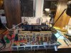
Anyway, I find solid measurements all over. Bias is rock steady. I managed to get the balance right with my cheap scope also.

I still have a lot of aesthetic work to do inside the unit. I would like to fabricate new covers for the big caps. Im thinking of using big shrinking sheets to copy the original covers. I find these kind of things satisfying :)

All contacts work fine, but I can see they are not perfect. Im not sure how to get all of them shiny, but I will try to gently polish them with qtip and alcohol.

Faceplate and wooden box is very nice. I will add some pictures when i start to assemble.

Now i admit it looks like a mess, but it will look very nice.

I received this amp 29. september. It took me four days to receive needed parts. I think I spent about five days to recap. About the same time to change out all 2SC401 transistors and other needed upgrades. The rest of the time, around 3,5 weeks, I have tried to understand this unit and fix the rest of the problems. So incredible frustrating.

I'm not sure I would have managed without your support elnaldo, so this unit will be dedicated to you the next 55 years :)
 

Attachments

  • P_20221108_212330.jpg
    P_20221108_212330.jpg
    90.5 KB · Views: 46
  • P_20221108_212115.jpg
    P_20221108_212115.jpg
    151.8 KB · Views: 47
Keep in mind that bias will be lower with the DBT and raise at full power. Adjust a low value with the DBT and make the final adjustment at full power.
 
Thanks, I set it to half, so its idling around 12mV measured between pin nr 3 and 4 from top, on the board. That would be through R224&R226 on left side and same on right side. I havent assembled anything yet, but will adjust again when i connect it to the power outlet. First i want to keep it running for some days on DBT, to see if resistors are consistent over time. I have no idea how long its been since this was in use.
The test speakers are small, old and easy to drive, I have good volume at 09-10 o'clock. I have seen others struggling with very low volume before 11-12 o'clock. When I feel confident everything is safe, I will try them on the cornwalls :)

A little bit on the side. I'm using a Peak Atlas transistor tester. On some of the output transistors, it says ''shunt resistor between B-E, HFE reading can me inacurate''. Do you know if that is still usable? I cant remember what replacements I put in, but it was a very close match. Even on Transition Frequency. I will check when I get home :)
 
Nice work Frank, sounds like you have been very busy on this Sony and great you have her up and running. They are nice aren't they, l have the 1120A.
 
Hi Oldsansui441 :) They really are nice!

Today i noticed a imballance in the channels. I think it was OK yesterday. Since C114 was bad the other day, I pulled the 3 brothers and sisters. Two of them was bad as well. They measured only fragments of 100pF. Replaced them with wima films, and now the balance is perfect again :)
Im betting there will be some more to do the next couple of days. Maybe I'll order some more wima and replace all in the equalizer board.There is only 14 left.
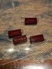
Adding a pic of the good, the bad and the 2x ugly 100pF film caps.

Its a PITA to get the faceplate back on. Think i have to modify some screws with square heads to make it easier. The screw head goes into a track in the faceplate. Then the 6 screws goes through chassis to be fastened with a nut on the inside of chassis. I can see now, from the drawing, there is supposed to be a screw with a nut head. I have the wrong screws then.. Makes sence.

The couple of outputs I replaced is BDY25C with identical HFE. HFE is low, compared to what I am used to. Measures from 9-11.
At least I think its a good match.
Pic of specs for both outputs
 

Attachments

  • 2SD45 replacement.png
    2SD45 replacement.png
    274.4 KB · Views: 37
  • P_20221109_215840.jpg
    P_20221109_215840.jpg
    120 KB · Views: 39
Hfe from 9 to 11 looks too low. Check the datasheets to see if they are within specs.

Datasheet from Internet specify hfe 15-45 minimum, and 75 minimum for the "C" parts.
 
Last edited:
Back
Top Bottom