• The move to the new server is done. There are some software and database maintenance updates in process. This has us passing the hat around to help out. We appreciate any donations. Seriously, even a dollar helps. The payment page may be found here - https://www.audiokarma.org/support.html

Oh no, Sony TA-1120

Can the low hfe reading be related to the shunt between B-E message on the peak atlas device. I have 10 ea BDY25C and five of them came up with the message 'shunt resistor between B-E, HFE reading can me inacurate'. Two of them had ''normal'' hfe around 80. I will try to measure resistance the old way.
Maybe my peak atlas isn't feeling well.That would be too bad, because I have matched all the replacement transistors for the 2sc401's.
 
Probably the low hfe reading is not accurate, but if the tester is reading a "resistor" between B-E, the part could have some leakage at that junction. If I were doing all that work on an amplifier, I'd use only transistors that check OK without any doubt.
 
OH, I have put all transistors with that reading to the side. Im just wondering if maybe some of the transistors without that reading also is slightly dodgy. It has happened when I check germanium transistors, that the test result is slightly wrong. I will see if I can test them in a circuit with maybe a diode.
 
Germanium tr have a leakage, that's nornal. But not in a silicon transistor. Just use the parts with regular readings.
 
Update, when listening today, I kind of wasn't impressed with the sound. I dont have any other way to describe as woolen sound. Not as clear and out of the speakers as expected. So I hooked up the Sony to another preamp and got a confirmation. So, Im still not quite there :)

Since I have changed all electrolytic caps and verified polarity, changed all the 2sc401 transistors and pulled the rest for testing, im thinking Mylar in EQ board or a resistor. Should i just replace the mylars or is it some way I can do diagnostic before I replace in the blind.
The left side sounds a lot more satisfying than the right side. There is also slight deviations in voltage on the transistors left and right side, both on EQ board and line board. Im convinced its the EQ board this time.(on the other side, im almost always wrong, or at least is feels like it)

Im using the preamp on a luxman 505x now, and sweet jesus, what control the sony amp has on the speakers! I had to connect to bigger speakers to confirm, but even on my test-speakers it sounded almost to good to to be true. Now I understand what the S/N ratio of more than 90db means.

So elnaldo, what do you think, replace the mylars on the EQ board? Its 7ea of them each side. (i dont want to think about those resistors yet...)
 
Mylar caps usually last "forever'...

These are the cases where an oscilloscope is needed. Not too easy to detect these kind of problems without one.

I'd be more inclined to suspect of tone control circuits, switches, and mistakes made in the recap process.

I'll check the schematic again and see what other ideas come to mind.
 
Last edited:
I also notice that when balance is centered at mid volume playing, rotating the balance to full left channel, the volume seem to go up a little.
Back to centre, volume goes down a bit. Never heard that before. The same happens to the right side, but not as much as left side. I think left side is OK, only problem with right side.
With a scope, will I be able to pinpoint where the signal gets weaker on this capacitor coupled layout? I thought that was a bit tricky. I do have a cheap scope.
 
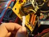
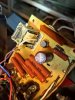
Just to have something to do, I will take out the reley and see how that looks. Will take some pics, since I cant remember seeing any online :)
 
If you have an oscilloscope capable of reading a 1KHz square wave with some accuracy, that's enought.

You can generate a 1KHz square wave with your computer, send it to the preamp, and check stage by stage if it keeps square or tilts to the left or to the right at some point.
 
If you are not familiar with oscilloscope usage, remember you can't connect the negative (ground) clip of the oscilloscope to any random point as you do with a DMM. Only connect the oscilloscope ground to the amplifier chassis or power supply ground point.
 
Today i noticed a imballance in the channels. I think it was OK yesterday. Since C114 was bad the other day, I pulled the 3 brothers and sisters. Two of them was bad as well. They measured only fragments of 100pF. Replaced them with wima films, and now the balance is perfect again :)

Hi Frank, nice you got the channel inbalance fixed up. I don't own a Peak atlas but l believe it is not possible to test the gain of an output transistor with these. Good idea to check the relay as you mentioned but didn't you verify that the poor sound was originating from the pre amp when using the Luxman?
 
Thank you oldsansui, yes it was confirmed to be the preamp. It sounded fantastic when i used the preamp from the luxman. Will have a go with the old scope now, to see if I can find the faulty component on the right side :)
The relay looked fantastic for the age. I only used paper with some contact cleaner to remove the lillte debris on the two contacts.
 

Attachments

  • P_20221111_150336.jpg
    P_20221111_150336.jpg
    91.9 KB · Views: 26
  • P_20221111_145924.jpg
    P_20221111_145924.jpg
    107.6 KB · Views: 25
  • P_20221111_145909.jpg
    P_20221111_145909.jpg
    81.1 KB · Views: 25
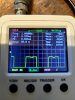
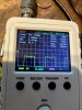
Im clearly not smart enough to use a scope. The only place i get a understandable reading is R147/247. I connected the ground to the chassis ground on the back panel of the chassis. Adding a pic of each channel measured on the mentioned resistor.
 

Attachments

  • P_20221113_151814.jpg
    P_20221113_151814.jpg
    92.5 KB · Views: 27
  • P_20221113_152230.jpg
    P_20221113_152230.jpg
    96.6 KB · Views: 26
Please measure the signal at the preamp out point (inside the unit or at the RCA connector) and at the volume pot input and output. That way you can start narrowing the problem.

That "anomaly" on the top of the wave is not normal but it's common to both channels. It could be the device itself or the original signal. Measure the source signal too, before connecting it to the amp.
 
Last edited:
OK, it was mylar C185 that gave the weaker, poorer sound in the right channel. I replaced it with a 0,001uf film cap and now, finally I have equal good sound in both channels :) I just started comparing voltages on left channel against right channel solderpoint to solderpoint.

Guess now i have to teach myself where to measure a square wave signal, and see if I can find out why my waves aren't perfect.
I can also meniton that when I ground the unit, the sound improves(at least it gets quieter). I use the ground plug on the back of the unit to ground it.

I would love to say I'm finished now, but finding a faulty mylar and those micas last week, makes me want to replace all of those also.

Ill sleep on it. Thanks again, you are the best help on the whole www!
 

Attachments

  • Mylar.jpg
    Mylar.jpg
    160.1 KB · Views: 27
Hi again! I feel i owe you a update :)
After my last post, i felt it was time so assemble everything and try it on the bigger speakers again.
After putting everything back together, I tested on DBT, all voltages seemed good.
I wasn't too confident, so I plugged it into the mains 240v without speakers and blue smoke came from left main amp board. It was all four emitter resistors that gave in.
-
I changed them out, measured the output transistors, and had to replace two of them.
Tested the rest of the transistors and diodes on the board and they all tested fine. Also checked all of the resistors against the healthy right board.
Testing again on DBT, plays nice, but when i measure bias over the two upper emittor resistors(R224&R226), I get 1,6mV.
When i measure over only one resistor, i get 22mv(guess that should be closer to 50mv, but I still run with a low bias). If i measure the bottom pair R223&R225, i get 15mV, as I want to have on the DBT.
-
Isn't that a bit strange...
-
I was thinking it had to be bad solder joint where the wires goes out from the power amp board. Thats where I measure bias, easy access. But I touched them up with same result. Also when I measured on solder joints over both resistors, 1,6mv.
Single resistor measurement 25mV.
-
-
Wait a minute, there is a diode on the printside of the board, connected to the emittor resistors. I havent measured that one!... It measured fine.
I will post again when i find the fault.
-
Oh, I forgot the most important thing. When I feel brave enough to connect to the mains again, is there anything i can check to make sure I dont get magic smoke again?
Turned out the last short was also due to my soft mica plates on the output transistors. I will swap with oldfashioned hard, thick silica plates.

 
You need to be measuring bias across only one emitter resistor at a time, e.g., R224, or R226, not both together...
The voltage drop across R224 should be 25mV, the same for R226, and even the same for R223, or R225.
If I've understood your measurement correctly, e.g., between pins 3 & 4 on the main amp board, then you should actually be seeing 0mV, under ideal conditions.
 
Last edited:
EDITED:
"When i measure over only one resistor, i get 22mv". That's OK
"Single resistor measurement 25mV". That's also OK.
 
Last edited:
If i measure the bottom pair R223&R225, i get 15mV, as I want to have on the DBT.

The 15mV you're measuring (assuming it's measured with the probes on connection points 3 & 4 from the bottom of the main amp board) is not what you want, on DBT or otherwise - you cannot measure the bias like that, and in fact 15mV like that would suggest a problem to me.

You have to measure one resistor at a time since you have 2 sets of parallel outputs, which each have their own bias current. The bias currents ideally should be equal in magnitude, that's partly what the 0.5R emitter resistors are for, but the bias current through R224 for example is not the 'same' current as through R226. The current thru' R224 passes via X117, while that thru' R226 is via X119.
 
Thanks for clarification, when you say it like that, its quite obvious! The way the resistors are arranged on the board, I was thinking they were two in series. o_O The good thing is that im getting good at being embarrassed :)
I will dive into why I have a voltage potential between pin 3 & 4. (Wich is between emitters on X118&X120)
 
Back
Top Bottom