• The move to the new server is done. There are some software and database maintenance updates in process. This has us passing the hat around to help out. We appreciate any donations. Seriously, even a dollar helps. The payment page may be found here - https://www.audiokarma.org/support.html

Ongoing saga of the Yamaha CR-n40s

Ha - no problem. No rush!

So - you're thinking that perhaps the power amplifier output module is bad... Hmm. I will try that test with the resistors... I'm not sure what I have in my stash. Just to be clear though, two equal value resistors on each pre-driver (one per pin - 13 & 14), running to their respective offset TP. Right?

If it turns out that it is the output module, then at least there are replacements available... though that doesn't help you with your test-bed much now, does it!

I'll keep you posted... probably won't get to it for a bit though. Unless the 8th day turns up soon...
 
> Just to be clear though, two equal value resistors on each pre-driver (one per pin - 13 & 14), running to their respective offset TP. Right?

Right.

Actually, though, I probably should have described an easier physical arrangement that's electrically equivalent. It'll be easier to tack the resistors onto the output module connections, especially with that module having been removed. On the output module, it's pins 1 and 10 (the outermost) that are involved. In this alternative, it's a little trickier to identify where the other end of the tacked-on resistors goes, but not bad - the point you're looking for is the junction of the two emitter resistors (the largish rectangular ones).

No worries if it turns out you don't need a replacement pre-driver.
 
That does sound easier. I might be able to try it Monday. Thanks!
Now to wrap my head around just what it is I'm doing electrically with the circuit... Am I basically fooling the pre-driver into acting like there is a good output module is in place when it isn't?


Sent from my GT-I9100 using Tapatalk 2
 
Yes, that's a reasonable description.

At the risk of TMI, I can go into some detail. One aspect of this test is that it re-establishes the overall negative feedback loop around the power amp section of the receiver. I believe this loop is broken now because the output module is bad (and it will certainly be broken when the output module is removed.)

"Closing the loop" will allow the pre-driver (if it's healthy) to do its job of monitoring the output of the power amp section, and making sure that the output is a faithful copy of the input. The DC voltage at the input is zero, so closing the loop should establish zero DC at the output. If that doesn't happen, it's a reasonably safe bet that the pre-driver is bad.

The main reason for inserting the pair of resistors is to limit the current that can be driven through the pre-driver in the unlikely event that there's something else wrong. But, they also afford us an extra sanity check. If the pre-driver is healthy, it should push a characteristic amount of current through those resistors. The current should be somewhere in the vicinity of five milliamps (0.005 amps). If you measure the voltage across the tacked-in resistors, it should be the product of that current times the resistance value. For example, 220 ohm resistors should develop about one volt.

Chatty chatty chazix
 
procedure check?

Ok... just making sure, and getting a couple pictures up here for future testers...

Here's the board where the power-packs sit, and the 4 emitter resistors. (big white ones, right?) (Packs removed, obviously)

IMG_20121001_104424.jpg


Flip over, here is the back-side of the same area.

IMG_20121001_104535.jpg


Test to confirm pre-drivers are functioning: Solder in 4 220ohm (aprox) resistors to connect the outermost power-pack connections (holes 1&10) to the point in the middle where the two big resistors share a connection - Indicated by red lines. The emitter resistor legs are indicated by blue curves...

CR-840+pre-driver+test.jpg


And just so I'm understanding, what this will do is make the pre-driver "see" a complete circuit where the power-pack is supposed to be - the circuitry inside the power-pack is replaced by the resistors where the red lines are, allowing the signal to flow normally even though the power-pack is removed. Resistors are used (instead of just jumpers) to prevent run-away current and burning out other parts. Correct? In this configuration, there will be some low level output from the unit? And as mentioned if 220ohm resistors are used, aprx 1v measured across each of the tacked in resistors. Powered on via dim-bulb of course for extra protection. :yes:

I'll probably get to this later this week... in the meantime, assuming that this confirms the likely scenario that the power-pack is pooched, does anyone know what the accepted replacement unit is? I believe there are STK subs that I've read about here somewhere. I'll see if I can find them too.
 
You are cleared for takeoff. Or should that be, on the glide path? Or should I leave aside lame attempts at aviation references? Anyway, the pictures and theory are spot on.

> In this configuration, there will be some low level output from the unit?

Yes. The protection relay should close, and the pre-drivers should be able to provide enough audio output for a listening test at low volume through headphones. Don't hook up speakers - they would present too low an impedance for the pre-drivers to deal with.

If you do find that you need an output module, I believe STK0060ii is appropriate for CR-840. They should be available from the suppliers who advertise here.

Cheers,

chazix
 
You are cleared for takeoff. Or should that be, on the glide path? Or should I leave aside lame attempts at aviation references? Anyway, the pictures and theory are spot on.


Thanks! It's nice to be learning some of the theory behind what I'm doing - graduating from simply finding busted parts and replacing them to actually understanding exactly what is going on.

Probably stick with the take-off reference... I'm still back a ways from approach to land at this point I think - once the dx is confirmed and parts ordered, then we'll worry about getting set up for landing! ;)

Good one though.
 
Ok... any experience with this company for STKs?

http://www.suburban-electronics.com/display/STK0060II/STK0060II

They're $10 cheaper than B&D... http://www.bdenterprisesinc.com/stk0060ii/

although, according to this (old) post... I should be looking for STK0070ii for the output on the 840...

......

The power amp modules are STK0050II, STK0070II and STK0080II respectively for the CR-640, 840, 1040 alltho you can use STK0060II in the 640. These modules are electrically identical, simply rated for higher voltages as you go up the numbers.

Rob
 
Last edited:
I'm not familiar with Suburban. I've used B&D for STK power packs satisfactorily.

Rob's knowledge of Yamaha trumps mine, so best go with the 0070 part.

Cheers,
 
I'm not familiar with Suburban. I've used B&D for STK power packs satisfactorily.

Rob's knowledge of Yamaha trumps mine, so best go with the 0070 part.

Cheers,

Will do... B&D it is. I've ordered some other stuff from them - tips for my 808. Should have ordered this too... oh well. Of course they don't have the 0070ii, but they do have 0080 which is supposed to be for the 1040, so I could just get a couple of those. Probably should replace in pairs I would think too...

I'll get the testing done tomorrow.
 
Sorry if this is too late, but I don't think there's any compelling reason to replace power packs in pairs. The failure of one implies next to nothing about the likelihood of the other failing. If they work properly, their influence on sonics is also next to nothing, so there won't be an audible left/right difference caused by replacing one at a time.

(Note that this case isn't related to the case of a power amp with a pair of discrete output transistors in each channel. In the latter situation, proper practice is to replace both transistors in a channel, even if only one has failed.)

Oh! On re-reading, I see that you are looking at replacing the packs with STK0080II - so, I take it that your thinking is that the 0080 might have characteristics different enough from the originals that you'd want to replace in pairs to keep the left and right channel matched. Thing is, the differences between parts in the series isn't in what they do to the audio signal, just in how much signal they're able to handle safely. So, if it was me, I'd still only replace the single failed part.
 
Last edited:
Nope... not too late. Haven't ordered anything yet.

I got the resistors tacked on today, 220ohm. Powered on with dim bulb, and all seemed well. No relay though... I started checking voltages, and that seemed to check out too. pins 13 and 14 on the pre-drivers had approximately symmetrical voltages of between 1 and 2 volts, +ve and -ve. They seemed to not want to stabilize though. So on to the DC offset, test points L & R to ground... and both had high values in the hundreds of mv, though one was +ve and the other -ve. They also were fluctuating wildly. So I started carefully adjusting the trim pots, and managed to get the fluctuation to center around 0mv, give or take... but they were still swinging in a 50 - 100 mv range. It's hard to give values due to the fluctuation. I also measured across the 2230 ohm resistors and got about 1.1 - 1.2 v on each.
I did have the input set to an open input, volume to zero, and DMM on DC mv... so I'm not sure what this means - I suspect something is awry somewhere, but now I'm stumped. And have other things to do... so more investigation will have to wait. :(
 
when and if your well planned and nice looking board is indeed working, you can count me in. I have a working 1040 that I would like to keep working. I will follow this post, thanks!
 
Hi, 4SeatPilot - I think it's beyond the scope of remote debugging to be certain about the fluctuation that you're seeing, but it's entirely possible that the receiver just won't be able to stabilize with the dim bulb rig. (What wattage bulb are you using?) You'll want to exercise your own judgment, but my take is that your observations are promising enough to warrant trying a higher-wattage bulb, or just plunging straight into a test with the receiver plugged in normally.

Hi, 68custom - the replacement board design works fine for me, I just think it's a good idea to get one tried out by someone independent before I claim "production readiness". Is your 1040 in need of a pre-driver at present?

Regards,

chazix
 
Oops, yet another reading comprehension problem on my part - I see 68custom's 1040 is currently working. I sure hope that not all x40s that need pre-drivers have gone to "for parts" status or worse!
 
Oops, yet another reading comprehension problem on my part - I see 68custom's 1040 is currently working. I sure hope that not all x40s that need pre-drivers have gone to "for parts" status or worse!

Fear not Chaz... I'm sure someone has one somewhere! I'm always looking for non-working Yamaha gear, so I might come up with one sometime too.

In the meantime, I'll try more watts. I had 65 watts in... (25+40) I'll go for 80, then maybe 100 before trying full-on.

Stay tuned... (I'm starting to think I should have a separate thread for this one now. If this doesn't work, I will probably do that)
 
I'm late to this thread. Had a CR-840 with a bad pre-driver and output pack, but ended up selling it cheap to another local AK'er. Don't know if he got it fixed. I'd like to find another CR-X40 and am interested to stay up on this pre-driver project.

Chazix: will you publish the schematic and p/n's you used if it works out? I'd even be interested in your PCB's if you make a batch, just so I have a couple around for when I do find a receiver.

Thanks,
John
 
Well, lateness is relative - merrylander kicked the thread off in 2008!

Yes, what I had in mind was to tuck away a schematic, board outline with part IDs, and the parts list I used somewhere (here?). For the board layout, what I had in mind was to make public the design data at BatchPCB, the prototyping service I used - they can take orders for one board, or however many you'd like.

I don't want to do that until I've had a chance to recover "entertainment costs" by selling a few built-up boards, though; and I'd like to get one independently tested before I go into "production".
 
...but it's entirely possible that the receiver just won't be able to stabilize with the dim bulb rig...
chazix

Yep! That was it. I had 65 watts in, so I put in another 40 instead of the 15, bumping it to 80. That improved things - the relay closed, and I had stable voltages - briefly. Then they started fluctuating again, so I plugged it straight into the wall. Bingo! Once it warmed up a bit, the voltages were stable and relatively easy to adjust to near 0mv. Both sides now hold within about 2.5mv of zero, so I'm pretty happy with that!

I then double checked the voltages at pin 13 & 14 of the pre-drivers, and got about 1.4v - one +ve, one -ve. So then I plugged in some headphones, tuned up a station... and voila. Audio! So all is well... just need a new power-amp unit. Though now that I have them off, I forget which one was on the side with the high DC... so I'll have to figure out how to test them while off the receiver.

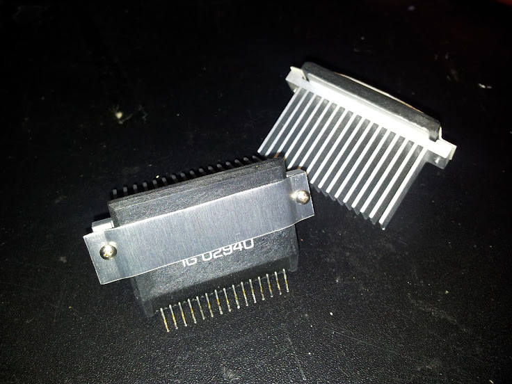
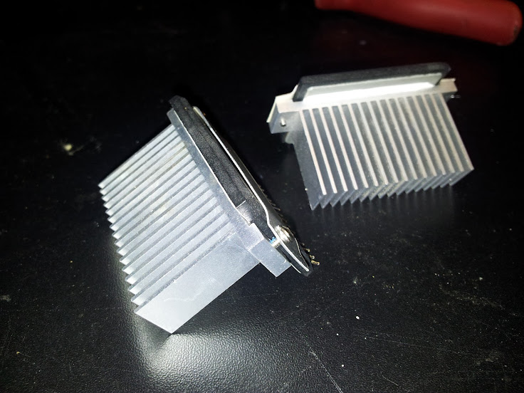
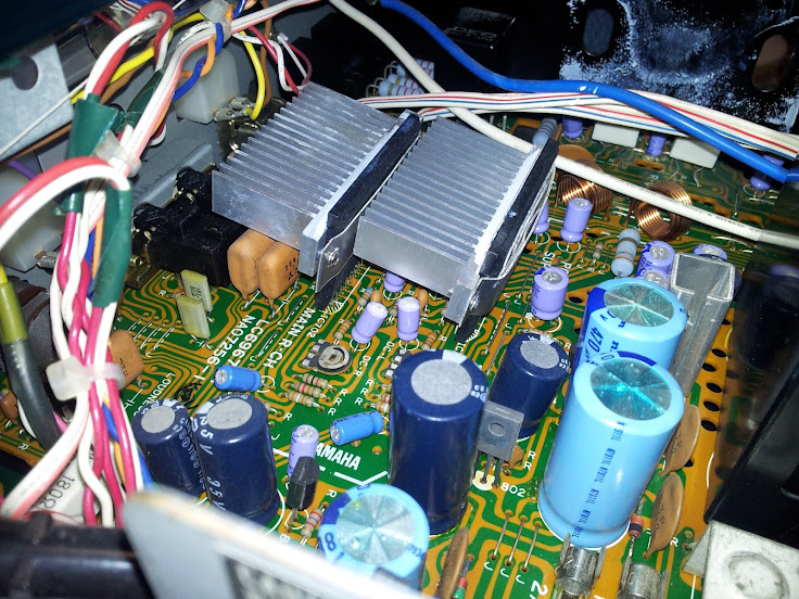
On to the heat issue of the pre-drivers... they got up to about 110F just while adjusting and testing. So I pulled some rather nice heatsinks off a couple computer motherboards, and they fit like they were designed for these things. Pics are worth a thousand words, so here you go.

IMG_20121009_220940.jpg


IMG_20121009_221018.jpg


IMG_20121009_223657.jpg


in retro-spect I should have replaced those caps underneath the one heatsink before I put the chip back in. Those are going to be a PITA to do now... :rolleyes:
 
Last edited:
Back
Top Bottom