• Please note that Audiokarma will be offline briefly for updates early on Monday morning, September 28th.

Ongoing saga of the Yamaha CR-n40s

.....
I don't want to do that until I've had a chance to recover "entertainment costs" by selling a few built-up boards, though; and I'd like to get one independently tested before I go into "production".

Even though it turns out I don't have any dead pre-drivers at this time, I would still be happy to test your board in my 840 and the 1040 if you want... they're both working so they would be valid test-beds.
 
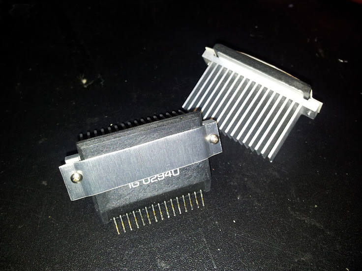
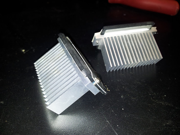
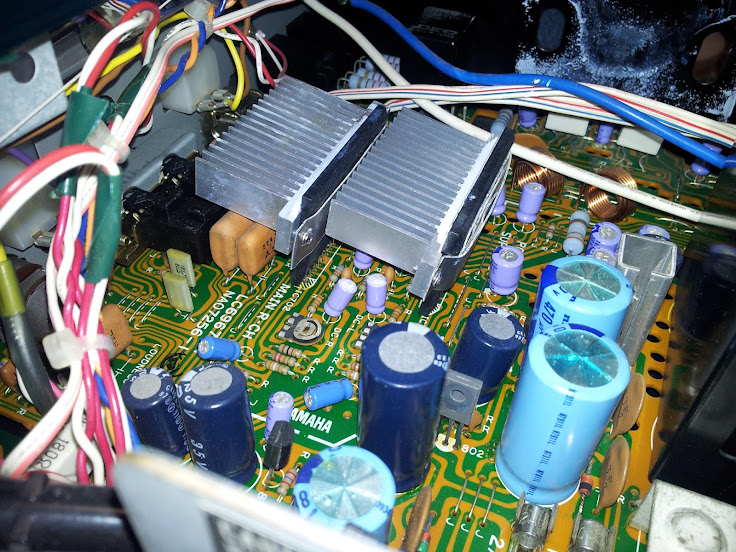
On to the heat issue of the pre-drivers... they got up to about 110F just while adjusting and testing. So I pulled some rather nice heatsinks off a couple computer motherboards, and they fit like they were designed for these things.

Can you say what brand of motherboard offered up those heatsinks? Looks like they could be useful.

thanks,
John
 
Can you say what brand of motherboard offered up those heatsinks? Looks like they could be useful.

thanks,
John

No kidding, eh?

It was a server board, found it in the e-waste... I think it's a Tyan S5397.

There were couple other useful sinks on it as well. I grab every old MB I can get my hands on, for just this type of thing. :D
This is the board sans heat-sinks, my cannibalization was total.

IMG_20121010_220941.jpg
 
Last edited:
You go, 4seatPilot!

For finding which output module is bad, I think we can be pretty sure that there's an open base-emitter junction somewhere among the three Darlington-connected PNP transistors that are inside the module. The BE junction of the final output PNP transistor is between pins 3 and 5. The two other PNP BE junctions are connected in series between pins 4 and 5. The classic ohmeter go-nogo test for semiconductor junctions should work for either pair of pins - I'm guessing you know how to do that?

You're very kind to offer, but to me it doesn't feel right to have you mess with a working receiver to test my pre-driver board. That would be a heck of a violation of the "if it ain't broke, don't fix it" maxim.

Cheers,

chazix
 
I presume you mean using the diode test...

Module 1 shows breakdown voltages I would expect to find across B-E junctions. +ve on pin 3, -ve on 5, 0.54v. Between 4 & 5 I get 1.22v which makes sense if there are two in series. Polarity is +ve on 5 and -ve on 4.

Module 2 shows almost a dead short on both those combinations.

I know you referenced a likely open junction, which initially to me means no conduction. However, it seems that module 2 has failed with shorts. Does that make sense??
 
Yes, diode test, and your interpretation of the readings makes sense.

So, it looks like I'm wrong about the failure mode. My reasoning was that, based on the voltage readings you took while the bad power module was installed, the pre-driver was trying to drive the output point negative, but in fact the output was positive. I leaped to the conclusion that, regardless of whatever else might be wrong with the output module, the path through the BE junctions in the PNP half of the module must be open.

There's (at least) one assumption I made that now looks wrong - did you get a chance to check the emitter resistors for continuity? If the bad power module is *shorted* through the PNP BE path, then I think that the associated emitter resistor must be open.

Adding the next afterthought: I see there are series resistors between the actual input pins of the power module and the bases. They might go open. On the PNP half, this resistor is between pins 1 and 4. I don't know what its resistance should be, I'm afraid, but the order of magnitude is probably in hundreds of ohms.

Afterthought to explain why the previous afterthought matters (given that you've already identified the bad output module, regardless of the exact nature of its failure): If the resistor between pins 1 and 4 of the bad output module has gone open, it was probably caused by excessive current that would have also passed through the pre-driver module. In that case, it might be warranted to replace the pre-driver, even if it still works. It's another judgment call sort of thing.

In any event, do be sure to check the emitter reistors - they are known to often fail in the aftermath of an output module failure.
 
Last edited:
fire and smoke! (or at least there was)

Umm, so yeah. The emitter resistors. They're supposed to be .47ohms... 3 of them measured .7 ohms, the other one about 100,000 ohms. I'll let you guess which one that was...

IMG_20121013_230733.jpg


And now guess where it was...


IMG_20121013_230602.jpg


That must have been a pretty big pop and spark! I bet whoever was standing by the receiver jumped out of their shoes. (if you can't see it, the big blue resistor on the right has a large burn underneath it. It looks twice as bad in person - the camera didn't capture it all) The burnt emitter resistor was in the position just above it, you can see some burn mark in the hole near the R. I'll try for a better picture tomorrow and edit the post if it works out.

So I guess I'll order some new .47 ohm resistors. :yes:

Now the only question is why did this happen? Did the resistor fail, causing what was obviously a large amount of voltage where is shouldn't be, so it sparked... and killed the output module? Or did some other failure push all that current through? Did someone short the speaker wires and cause the over-current? :dunno:

The test with the jumper resistors gave good stereo audio through the headphones, so I'm inclined to think that I've found the failed parts... and with a new output, and new .47 ohm resistors we'll be off to the races. But if anyone wants to suggest anything else I should check... :scratch2:
 
My take is that you'll be all set with the output module and the resistors.

The proximate cause of the toasted emitter resistor would have been excessive current running through it, and that was probably caused by a collector-emitter short in one or both of the final output transistors that are inside the output module.

Whether the transistor failure was, in turn, due to an external overload like a shorted speaker connection is anybody's guess.

chazix
 
That was my thinking too. Thanks for confirming. :tresbon:
I have a couple other things to order from BDent anyway, so I'll add the amp module to the order and see what they have for .47ohm resistors too.

Tolerance on the originals was pretty loose I guess - I pulled 4 identical ones from a Toshiba receiver that I cannibalized, and though they were labelled .47ohm, they all measured 1ohm. Weird....

dgwojo is working on a bulb order for me, so we'll be all set soon!
 
Last edited:
The good news is that a volunteer came forward who was in a position to test one of my replacement modules. The test patient was a CR-640, and the repair was successful, with no trouble other than bending the heat-sunk transistors a bit to clear the dial scale lighting terminals. (CR-640 has a little less elbow room inside than the bigger receivers.)

My thanks to Peter at The Stereo Doctor in Augusta, Maine for being the brave volunteer and supplying great feedback.

The bad news is that this ends the offer of a freebie module. I plan to try to sell a few to recover my entertainment costs, and then post DIY info somewhere in this forum. So, if you're in a hurry or aren't prepared to build up your own module, keep an eye on that four-letter-word auction site. Otherwise just stay tuned here.

Happy holidays,

chazix
 
Looking forward to picking up one or two kits (or at least the PCB) from you. :)

This could mean the resurrection of quite a few doorstops!
 
Hi all,

I wanted to add my experiences so far trying to resurrect a CR-840. First, I'd like to say "thank you" to Merrylander, Chazix, and 4seatPilot for all their posts that have been very helpful to me in troubleshooting this receiver.

Like most everyone who has a non-working one of these, mine would not come out of protection. Following Merrylander's instructions, I discovered highly positive DC voltage (more than 40 volts) at the TR test point. I then checked pins 13 and 14 on the driver module--also highly positive.

At this point I was assuming I had a bad driver module. However, after rereading this thread I decided to follow Chazix's instructions and remove the output module. After removal, I still had high voltage at pins 13 and 14, but the readings were opposite and symmetrical (about +42 on pin 14 and -42 on pin 13).

Next, I followed Chazix's instructions and 4seatPilot's photos to install two resistors (I used 1000 ohms) to bypass the missing output module and complete the feedback circuit. Magically, this lowered pins 13 and 14 to about -6 and +6 volts respectively. The protection relay pulled in, and I had music on that channel into my son's 250 ohm headphones.

So, I am now assuming that my driver module is still good, and I should be back in business once I replace that channel's output module and emitter resistors.

The two lessons I wanted to add to this thread are:

First, high voltage on pins 13 and 14 could be a failure of either the driver or the output module, so don't assume the hard to find driver is bad without further testing.

Second, voltages on a good driver will be high but symmetrical after removal of the output module unless the jumper resistors are used.

Best,

Dan
 
Last edited:
Heaviside - I think you may have posted what I needed to see ... the electronic knowledge on this site has me cowering in the corner going "I dont deserve to open this amp, I dont deserve to get this amp working, I dont understand none of this, god help me"

Thanks much.
Cool.
Srinath.
 
Allen head

Yep! That was it. I had 65 watts in, so I put in another 40 instead of the 15, bumping it to 80. That improved things - the relay closed, and I had stable voltages - briefly. Then they started fluctuating again, so I plugged it straight into the wall. Bingo! Once it warmed up a bit, the voltages were stable and relatively easy to adjust to near 0mv. Both sides now hold within about 2.5mv of zero, so I'm pretty happy with that!

I then double checked the voltages at pin 13 & 14 of the pre-drivers, and got about 1.4v - one +ve, one -ve. So then I plugged in some headphones, tuned up a station... and voila. Audio! So all is well... just need a new power-amp unit. Though now that I have them off, I forget which one was on the side with the high DC... so I'll have to figure out how to test them while off the receiver.

On to the heat issue of the pre-drivers... they got up to about 110F just while adjusting and testing. So I pulled some rather nice heatsinks off a couple computer motherboards, and they fit like they were designed for these things. Pics are worth a thousand words, so here you go.

IMG_20121009_220940.jpg


IMG_20121009_221018.jpg


IMG_20121009_223657.jpg


in retro-spect I should have replaced those caps underneath the one heatsink before I put the chip back in. Those are going to be a PITA to do now... :rolleyes:

If you had allen head bolts holding the heat sink on the chip, you can take it off with it still in the circuit board.
Cool.
Srinath.
 
Interesting to see that Utsource is offering IG02950 (the CR-640 pre-driver) on ebay. And at a price that must be way less than whatever Yamaha listed back in the day. I wonder if they can be genuine? Utsource themselves seem to have an OK reputation, but I imagine it's possible for them to be fooled by counterfeiters. Anyway, at the price they're offering, I ordered one just to see if I can figure out if they're real. Will report my findings here.

(No affiliation with Utsource.)

chazix
 
If you had allen head bolts holding the heat sink on the chip, you can take it off with it still in the circuit board.
Cool.
Srinath.

True.... I used the original screws that held the sink onto the computer board though.

Oh well, I'll figure it out.
 
Can I use the 640's pre driver on a 1040 ?
I have a line on a 640 I could get parts from, but my dead amp is a 1040.
Thanks.
Srinath.
 
The CR-640 pre-driver would not be guaranteed to survive the higher voltages used in the CR-1040, so it's not something that I would try.

Are you sure that your CR-1040 pre-drivers are bad?
 
I received the IG02950 (CR-640 pre-driver) that I ordered from utsource on ebay in 2 1/2 weeks. (They are in Hong Kong.) My verdict: I believe it's a genuine made-for-Yamaha part, presumably NOS.

At first glance, I noticed that the lead frame is flat-stamped instead of cylindrical wires as I've seem on all the parts I've seen installed in receivers. That got my counterfeit detector buzzing. But then I cut off the top cover (carefully, so as not to damage printed wiring or components). Inside, I was delighted to see not only the THREE compensation capacitors that make this pre-driver circuit quite different from any generic one, but in fact all the components and printed wiring looked virtually identical to a part that I've removed from a receiver myself and opened up.

Electrical testing also confirmed that this is the real deal. The example I got was a bit lower in open-loop gain than the pulled part I have (and also, he said with a blush, a bit lower than my home-brew implementation of the big-brother IG02930). But open-loop gain isn't tightly specified; as long as it's "a lot", it will do the job when it's used in a closed-loop feedback circuit. So that characteristic seemed fine. The final stage of the amplification section, which uses a constant-current source, pushed the expected current (about 6MA) through my test rig. The other circuit section, whose job is to limit current in the power stage, also worked as it should.

I've ordered another. I would encourage anyone who has a CR-640, or who thinks they might have or work on one someday, to do likewise. The price UT is asking for them is insanely cheap, and getting them into the hands of the Yamaha enthusiast community is a good way of keeping some distributor from cornering the market and jacking the price.

I have no relationship with UT other than as a satisfied customer.

Cheers,

chazix
 
Back
Top Bottom