• The move to the new server is done. There are some software and database maintenance updates in process. This has us passing the hat around to help out. We appreciate any donations. Seriously, even a dollar helps. The payment page may be found here - https://www.audiokarma.org/support.html

Onkyo M-508. A couple of questions for the experts

OK, got a chance to get back to this.
300w DBT and dimmed normally. Ruling out any "dead" shorts
I had reduced the BIAS (CCW) some before flipping the switch, and it began from zero and rose to a few mV.
Waited a few minutes and it remains in orange protection. No relays clicked and no "magic smoke" or "hot smells".
So it seems more digging, pulling, and testing components will be necessary. I read someone found a bad transistor in the servo causing it, but didn't mention which one.
 
Nope, I don't have that, but above the Avatar I have a block for "status message" but it didn't change anything. Mine also also has the gender / DOB blocks, just no "Custom Title".
@Binkman might be on to something I hadn't noticed. It's possible you need to be a subscriber to access certain "features" in your profile. I can't test that theory until my subscription expires though. :D
 
My trick is I set the Bourns pots to the same resistance as the originals when I install them and use that as a starting point. Then I don't have to worry about which direction is minimum and risk getting it wrong. Sometimes the direction ends up reversed when I install the Bourns.
Yes, I do that quite often too. But in some cases, like this one, I like to be sure which direction is needed to reduce BIAS current. I also like it to match the SM (when applicable) so whoever gets to work on the unit again will have no surprises. Although I have used Bourns that work opposite, I tend to keep those in DC Offset where it wouldn't hurt anything either way.
 
So I had a buddy take a look at my M-508 (retired Navy electronics tech and current dabbler in stereo repair) with his fancy test equipment and he confirmed that my issues appear to be related to bad relays, so I'll change those soon. He did discover that the main rails are running at 86+ volts, not the 75 volts the service manual calls for.. very weird, but it may explain why the 10,000uF 90 volt filter caps have gone bad twice. His opinion is that the design of the amp is based on the Japanese electric system of 100 volts and when used in the U.S. with 120 volts it can raise the rail voltage... I'm not sure I agree as mine is the switchable 120/220 version... any thoughts pro or con? Is it some other component causing the rails to run 10 volts higher than spec?
 
So I had a buddy take a look at my M-508 (retired Navy electronics tech and current dabbler in stereo repair) with his fancy test equipment and he confirmed that my issues appear to be related to bad relays, so I'll change those soon. He did discover that the main rails are running at 86+ volts, not the 75 volts the service manual calls for.. very weird, but it may explain why the 10,000uF 90 volt filter caps have gone bad twice. His opinion is that the design of the amp is based on the Japanese electric system of 100 volts and when used in the U.S. with 120 volts it can raise the rail voltage... I'm not sure I agree as mine is the switchable 120/220 version... any thoughts pro or con? Is it some other component causing the rails to run 10 volts higher than spec?

Relays do go bad and many times the failures are not readily apparent. Relay thread.

Operating with 86V on a 90V rated cap shouldn't be a problem. I've seen a lot worse on some amps with caps that were 30+yrs old. As an example, I have worked on a lot of Acurus A250 amps (dating from the early to mid 90's) and those have 95V rated primary caps and they typically run 90 - 93V on the rails. I've seen very few of those with main cap failures. The big thing to watch for outside of the quality of the cap is the heat its exposed to. Try a set of Kemet's which have a 105C rating and a lengthy 20,000hr or more rated life. I've been using them in the amps I've refurbed over the past few years and the quality seems very good for the price.
 
So I had a buddy take a look at my M-508 (retired Navy electronics tech and current dabbler in stereo repair) with his fancy test equipment and he confirmed that my issues appear to be related to bad relays, so I'll change those soon. He did discover that the main rails are running at 86+ volts, not the 75 volts the service manual calls for.. very weird, but it may explain why the 10,000uF 90 volt filter caps have gone bad twice. His opinion is that the design of the amp is based on the Japanese electric system of 100 volts and when used in the U.S. with 120 volts it can raise the rail voltage... I'm not sure I agree as mine is the switchable 120/220 version... any thoughts pro or con? Is it some other component causing the rails to run 10 volts higher than spec?
I think the problem with the caps stems from how tightly they are snuggled together leaving little room for air flow. At least the originals are anyways. Being at 86+ volts kinda sets up an alarm with his equipment being possibly out of calibration. Fancy or not, it can happen. About the only other thing, besides the transformer windings that can raise the voltage, is line voltage, or weak center tap ground. Mine here frequently reaches 124+ and you have to take that into consideration when checking unregulated power supplies. 86+ still sounds a bit high either way even if line voltage is at 124+. I hope to get the time in a few days to get back on this one. I'll check the rail voltages first thing. This one is also switchable 220/120v.
 
Relays do go bad and many times the failures are not readily apparent. Relay thread.

Operating with 86V on a 90V rated cap shouldn't be a problem. I've seen a lot worse on some amps with caps that were 30+yrs old. As an example, I have worked on a lot of Acurus A250 amps (dating from the early to mid 90's) and those have 95V rated primary caps and they typically run 90 - 93V on the rails. I've seen very few of those with main cap failures. The big thing to watch for outside of the quality of the cap is the heat its exposed to. Try a set of Kemet's which have a 105C rating and a lengthy 20,000hr or more rated life. I've been using them in the amps I've refurbed over the past few years and the quality seems very good for the price.

I've been looking at various caps for this thing for quite awhile - the Nichicon caps that fit (when you can find them) have a low ripple current capacity, the United Chemi Con caps have higher ripple current, but again very hard to find -Mouser is expecting some in December- (that 35mm diameter really restricts the selection)
https://www.mouser.com/ProductDetai...wFf0viD3Y3a3yb5D6sPUg61FOOhXMnUM7QFDzxVkUfQ==
 
I've been looking at various caps for this thing for quite awhile - the Nichicon caps that fit (when you can find them) have a low ripple current capacity, the United Chemi Con caps have higher ripple current, but again very hard to find -Mouser is expecting some in December- (that 35mm diameter really restricts the selection)
https://www.mouser.com/ProductDetail/United-Chemi-Con/ESMH101VND103MA63U?qs=sGAEpiMZZMvwFf0viD3Y3a3yb5D6sPUg61FOOhXMnUM7QFDzxVkUfQ==
That's also why I have been in no hurry. Finding the proper caps at a reasonable cost has been a strike-out. Internal leakage could account for the current draw. Checking the "off" voltage reveals a pretty quick drain down. The current draw could be what's keeping it in protection. But I am admittedly not familiar with this particular design at all.
 
My newly acquired (from my brother) M-506RS uses four 22,000uF 69 volt caps on a 50 volt rail and I have never heard of one of these having problems with the caps going bad- I wish they would have kept this set up in the 508...

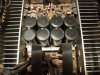
005.jpg
 
Last edited:
I've been looking at various caps for this thing for quite awhile - the Nichicon caps that fit (when you can find them) have a low ripple current capacity, the United Chemi Con caps have higher ripple current, but again very hard to find -Mouser is expecting some in December- (that 35mm diameter really restricts the selection)
https://www.mouser.com/ProductDetail/United-Chemi-Con/ESMH101VND103MA63U?qs=sGAEpiMZZMvwFf0viD3Y3a3yb5D6sPUg61FOOhXMnUM7QFDzxVkUfQ==

OOPS, these are the ones... 10,000uf/100v 35mm diameter...

https://www.digikey.com/en/products/detail/cornell-dubilier-electronics-cde/382LX103M100A082/2295343
 
Those look like they could work very well: CDE # 380LX103M100A082: 10,000uF, 100V (125 surge) 35mm X 80mm (a little short, but that is fine). They have a low ESR (at 25C @ 120 HZ =0.033, and @ 20Khz = 0.025), plus a decent ripple (at 85C @ 120hz= 8.70, @ 20Khz= 9.60). The Nichicon ones in there now (from 1999) only have a ripple of about 5.5 so these CDE ones would be far superior.
 
Those look like they could work very well: CDE # 380LX103M100A082: 10,000uF, 100V (125 surge) 35mm X 80mm (a little short, but that is fine). They have a low ESR (at 25C @ 120 HZ =0.033, and @ 20Khz = 0.025), plus a decent ripple (at 85C @ 120hz= 8.70, @ 20Khz= 9.60). The Nichicon ones in there now (from 1999) only have a ripple of about 5.5 so these CDE ones would be far superior.
I ordered some today. 4 pin, but as the old Midas commercial went.. "We'll make it fit". :D
 
So I had a buddy take a look at my M-508 (retired Navy electronics tech and current dabbler in stereo repair) with his fancy test equipment and he confirmed that my issues appear to be related to bad relays, so I'll change those soon. He did discover that the main rails are running at 86+ volts, not the 75 volts the service manual calls for.. very weird, but it may explain why the 10,000uF 90 volt filter caps have gone bad twice. His opinion is that the design of the amp is based on the Japanese electric system of 100 volts and when used in the U.S. with 120 volts it can raise the rail voltage... I'm not sure I agree as mine is the switchable 120/220 version... any thoughts pro or con? Is it some other component causing the rails to run 10 volts higher than spec?
I had a few moments to check the rail voltage. At 123vac incoming today, the rails were right about 79.5 with a wee bit of fluctuation. SM calls for 75v. So it's in the ballpark. Cut power and it took about 20 seconds to drain down to less than a volt. Except one set of caps stayed about 5v and slowly bled off. I would think the caps should all bleed off the same in this? I didn't see any bleed resistors in the SM, unless I just didn't see them. My copy isn't the "best" scan if you know what I mean. It's also chopped up like a jigsaw puzzle. :D
I got the new 100v caps in today so I plan on removing the old, clean things up, then check some things before "make it fit" installing the new ones while they are out of the way.
 
80 volts is better than my 86 volts...but still not enough "room" for the stock 90 volt caps IMO. Those 100 volt ones you ordered should do just fine.

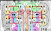
The two front center caps have a weird wiring configuration (on the circuit board) take a look at how they are hooked up in the diagram in the service manual (different than all the others). Seems as though those two are the ones that go bad first.

PCB 3.jpg
 
80 volts is better than my 86 volts...but still not enough "room" for the stock 90 volt caps IMO. Those 100 volt ones you ordered should do just fine.

The two front center caps have a weird wiring configuration (on the circuit board) take a look at how they are hooked up in the diagram in the service manual (different than all the others). Seems as though those two are the ones that go bad first.

View attachment 2584641
Oh yeah, the ones I got will do just dandy. I have to decide on the method of mounting them. The plate will come out and get carved out no matter what and reinstalled. It is needed as a stiffener to hold the weight of the 8 caps off the board. I saw how you did it, then ran jumpers to the separated traces. I may use solid 14ga copper wire to mimic the original 4 lead pattern. Maybe glue some O-ring pieces to the bottom of each cap for adding a little space between them and the plate to increase air flow and insulate them from the heat sink heat that transfers to the plate.. That heat, in turn, transfers to the caps.
There was no reason to separate the traces like that since they lead back to the same pin on the cap(s) anyways. It just gives the "illusion" of having separate L/R traces. Solid traces would have made for a "new" solid solder pad for each by simply drilling new holes on center line.
I am going to remove the heat sinks anyways to re-grease the transistors, and test them for consistency out of circuit. I have spares in the event Justin Case comes knocking on the door, :D
 
Back
Top Bottom