• The move to the new server is done. There are some software and database maintenance updates in process. This has us passing the hat around to help out. We appreciate any donations. Seriously, even a dollar helps. The payment page may be found here - https://www.audiokarma.org/support.html

Onkyo M-508. A couple of questions for the experts

The MUSE capacitors come in both Polar and Non-Polar. The ES are the non-polar version.

https://www.nichiconcapacitors.com/product-category/nichicon-es-series/

https://www.nichiconcapacitors.com/nichicon-kz-muse-series-audio-capacitors/

It's a "waste", but the non-polar should work fine.

Ok, Thanks...I'll use the bi-polars caps. They only cost $0.84 each, while regular polar caps are $0.50 each. Mouser's shipping is not cheap - it would cost me $8 to ship $2 worth of capacitors !
For some reason I thought all MUSE caps were bi-polar, I didn't know they were just better grade
 
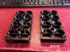
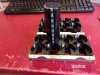
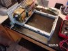
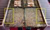
The New CDM main filter caps arrived today- had to snip off the two "dummy" leads then grind down the nubs with my dremel so the caps would sit flat in the new capacitor block. Also made new copper plates to hold everything together. I have to go to the hardware store tomorrow and get some solid 14 ga copper wire to make the leads with.
new CDM caps 002.jpg new CDM caps 003.JPG new copper plates 001.JPG

*** if anybody is interested in the old caps you can have them for the cost of shipping only - just send me a PM. They were working fine, were made in June 1999, and can keep your old M508 going for a few more years without too much work to put them in. They would also work as an "upgrade" to the M504 that uses the 9,000uF caps.
 
Last edited:
Had zero luck today trying to find some simple 14 gauge solid copper wire... went to Ace, Lowes, Home Depot, and four auto chains and came up empty. You would think in a metro area with 3/4 of a million people somebody somewhere would have some plain old wire solid copper wire, but NOOOO (only 4, 6, 8, and 20 ga, either way too thick or way too thin). I ended up ordering some 14 ga coated wire from Amazon that I'll have to soak in lacquer thinner for a while to get rid of the coating.
 
Had zero luck today trying to find some simple 14 gauge solid copper wire... went to Ace, Lowes, Home Depot, and four auto chains and came up empty. You would think in a metro area with 3/4 of a million people somebody somewhere would have some plain old wire solid copper wire, but NOOOO (only 4, 6, 8, and 20 ga, either way too thick or way too thin). I ended up ordering some 14 ga coated wire from Amazon that I'll have to soak in lacquer thinner for a while to get rid of the coating.
Yep, 12, 14, and 16ga Romex (2 conductor plus ground) are the most commonly used for residential construction. 16/3 w/ ground can be used too. You'll just have "extra" pieces leftover. But more choices of color. :rflmao:
 
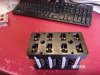
The new CDM 10,000uF 100 Volt main filter caps are finally installed (mostly), a little touch up is needed on a couple of the pins before I install the new copper plates (installed for test fitting only right now) and snip off the excess wire- probably tomorrow (my eyes are tired!) I will replace the small value electrolytic caps and all new power transistors next week
5. new CDM cap wire leads 004 .jpg 6. new CDM caps installation.jpg 7. new CDM caps installation.jpg 10. new copper plate fitting.JPG
 
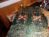
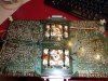
New main cap install completed, old output transistors removed (all measure fine, I'll keep them as spares). I ended up with three bad trace ends at the pins, two I fixed by removing the green backing down to the copper and made a solder bridge, one of them was too sketchy that way (I didn't trust it to last) so I just put in a jumper.
11. New copper plates -final.JPG 12a. bad trace.jpg 12. jumper to cap pin.JPG
 
New main cap install completed, old output transistors removed (all measure fine, I'll keep them as spares). I ended up with three bad trace ends at the pins, two I fixed by removing the green backing down to the copper and made a solder bridge, one of them was too sketchy that way (I didn't trust it to last) so I just put in a jumper.
View attachment 2616506 View attachment 2616507 View attachment 2616508

I found a couple of bad traces/pads on this one too. I had to jumper them to be sure they were all good. Two solder pads were cracked and floating. I then raised the copper squares a bit, used a set of hemostats to kelp keep the heat from desoldering the solder at the traces. Then left about 1/4 inch when snipping the leads off. That leaves "test points", and places to solder the rest of the wires on. There's plenty of space between them and the bottom cover. I left the board in, but pulled the heat sinks w/ transistors. Everything tested fine and the grease was still "wet". I put them back in before installing the caps. Perhaps I'll get a chance to fire it up today and see if it smokes or not. :beatnik: I've had so much other "more important" stuff to do lately it's driving me nuts. :crazy: :rflmao:
 
One of the output transistor pads on mine is a bit weak (cracked) I'll have to be very careful with it. Check all the solder joints on your bottom board, I'm seeing several spots on mine that should be considered cold solder joints (cracked 1/2 way around but still functional). The front (meter) board looks to be in much better condition.
 
One of the output transistor pads on mine is a bit weak (cracked) I'll have to be very careful with it. Check all the solder joints on your bottom board, I'm seeing several spots on mine that should be considered cold solder joints (cracked 1/2 way around but still functional). The front (meter) board looks to be in much better condition.
Already did that. I found about 30 or so bad looking ones, and went ahead and hit a bunch more that looked like their time was approaching. Take a thicker piece of component lead snippet, scratch back the green, tin the trace, then bridge across the crack. I had one transistor pad looking a bit iffy too. I might go ahead and pull the front board again and do more checking before I try to power it up. Ya never know, a second look might reveal something missed the first time around when I replaced the bridge rectifier..
 
Question for Skywatcher: I've replaced all the small caps on the main board (and reflowed 47 joints that looked suspicious) but I'm have trouble with the joints on C451 & C452 (caps) flowing into D451 & D452 (diodes). They were all separate joints from the factory, but they are so close together that I can't keep them separate. The underlaying copper trace all looks to be one block that eventually goes to one of the legs of transistors Q441 and Q442.... so is it alright to leave them connected or do I need to get out a file and separate them? (my copy of the schematic is too hard to read).

C451 D451 Q 441.jpg C452 D452 Q442.jpg
 
Last edited:
Question for Skywatcher: I've replaced all the small caps on the main board (and reflowed 47 joints that looked suspicious) but I'm have trouble with the joints on C451 & C452 (caps) flowing into D451 & D452 (diodes). They were all separate joints from the factory, but they are so close together that I can't keep them separate. The underlaying copper trace all looks to be one block that eventually goes to one of the legs of transistors Q441 and Q442.... so is it alright to leave them connected or do I need to get out a file and separate them? (my copy of the schematic is too hard to read).
Looks like they are all on the same pad/trace so it won't matter if the correct leads are soldered together.

Partial schematic 508.jpg
 
Looks like they are all on the same pad/trace so it won't matter if the correct leads are soldered together.

View attachment 2623227

Thanks a TON-- I was a bit worried that I would let the smoke out the first time I fire it up ! I have to recap the Meter board this week then put it all back together. Fortunately there are not very adjustments to make once it passes the dim bulb test.
 
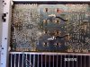
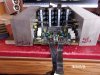
I made good progress today: main board is all done, heat sinks were installed and the new output transistors were soldered in place. I had to reflow almost every joint on the rear half of the board, but it is finally it is ready to reinstall into the bare chassis. I got half way done with the meter board this afternoon, should (I hope) finish that up tomorrow. When tearing it all down I discovered it would be easier to reinstall the front meter board before the main board/heat sinks.
15. bare chassis.jpg 16. completed board- front.jpg 17. completed board- rear.jpg 19. heat sinks installed.jpg 21. Output Transistors close up.jpg 22.  ready to install.jpg
 
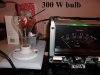
So, it is all back together (no smoke !), and it came out of protection on the Dim Bulb tester with a 150 Watt bulb and a 300 watt bulb (both dimmed down to nearly nothing). I let it sit on the 300 watt bulb for an hour then went straight to regular wall power to set the idle current. The left channel gets very warm, idle current set to 15mV per manual, but the right channel is stone cold with no reading on the idle current... so I messed something up somewhere but don't know where to start looking.... going to leave it be overnight, maybe I'll see something obvious tomorrow morning with a rested set of eyes.


109_2784.jpg 109_2783.jpg
 
Last edited:
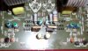
No time today for much troubleshooting, but a quick visual inspection shows diode D418 is not "lit up" (it is one of the LTZ-MR15 LED ones that is supposed to glow red). It is the one right in front of the trim pot, but I cannot find it on the schematic for the 120/220 volt models (or any of the other ones for that matter) so I can't where it goes... could this one little diode cause the lack of idle current? (pic is before recap)
bad diode D418.jpg
 
No time today for much troubleshooting, but a quick visual inspection shows diode D418 is not "lit up" (it is one of the LTZ-MR15 LED ones that is supposed to glow red). It is the one right in front of the trim pot, but I cannot find it on the schematic for the 120/220 volt models (or any of the other ones for that matter) so I can't where it goes... could this one little diode cause the lack of idle current? (pic is before recap)
View attachment 2625139
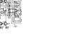
The schematic shows the one channel D417/419 so D418/420 are on the other channel in the same position.

D417 and 419.jpg
 
Did you test the LED? I wouldn't suspect the LED has suddenly failed especially since you just completed all of this work. Due to the fact you were working inside I would expect that something is mechanically open in the bias circuit somewhere, either a trace or a wire. I've seen this a happen in amps similar to this that have a separate circuit board for the bias transistor. Check all the wires leaving the main board traveling to the small daughterboard for the bias transistor Q443 are they well seated in the connector and still soldered to the daughterboard?

Per the schematic,
Whats your voltage drop across R421 and is it changing when you move the bias adj pot? How does this V drop compare to the same resistor in the working channel?
Whats your voltage drop from the Anode of D417 to the cathode of D419, in both the working and non-working channel?
 
Back
Top Bottom