• The move to the new server is done. There are some software and database maintenance updates in process. This has us passing the hat around to help out. We appreciate any donations. Seriously, even a dollar helps. The payment page may be found here - https://www.audiokarma.org/support.html

Oscillation Explosion!

KeithTr

AK Subscriber
Subscriber
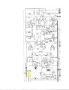
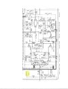
I thought I had fixed a Technics SU-V5 with a blown channel, had it running for a few days and apparently it went into oscillation (I'm thinking high frequency) and blew up the RC network (10ohm, .047uf) components (a combined package) on both channels. Schematic of that section attached. Most of what I replaced was pretty standard, but I did use film caps 1uf replacement and did substitute a few transistors (outputs were same as originals that blew previously). Also had used a newer opamp (of same class) for feedback circuit, which I'm thinking might have been the cause.

Since I've not dealt with oscillation before, wondering if anyone has a suggestion or two about how to diagnose the culprit(s) and a possible solution. Thanks in advance..K
 

Attachments

  • Technics V5 amplifier section of Schematic_2.jpg
    Technics V5 amplifier section of Schematic_2.jpg
    106.2 KB · Views: 26
  • Technics V5 amplifier section of Schematic_1.jpg
    Technics V5 amplifier section of Schematic_1.jpg
    101.8 KB · Views: 26
Register to hide this ad
Exactly, what did you replace and with what? If you used a higher speed opamp, you need local decoupling to prevent oscillations.
Or put back the original opamp, but local decoupling never hurts. 100nF x7r mlcc across the power pins.
 
Maybe list what was original and what you put in it's place.
most of what i replaced was non-controversial - electrolytics of same value (a few a bit higher voltage due to what was on hand), a couple of low value (1uf) caps with film caps, transistors (mostly outputs or drivers that were replaced with NOS - not modern replacements), and a couple of signal transistors with modern replacements. And I did replace the opamp which I believe is in the protect/dc regulation circuit. That could have been the issue though it was a modern version of the older chip. Will try to get to today or tomorrow and report back.
 
Exactly, what did you replace and with what? If you used a higher speed opamp, you need local decoupling to prevent oscillations.
Or put back the original opamp, but local decoupling never hurts. 100nF x7r mlcc across the power pins.

Thanks for the suggestion - when you say 100 nanfarads x 7(ohms? ceramic?) across the power pins (of the opamp?). Always something new to learn - now i have to go see what local decoupling really means. :thumbsup:
 
100nF = 0.1uF, x7r is the temperature coefficient. Local decoupling mean placing capacitors right at or as close as you can get, to the power pins Vcc(+), Vee(-) or ground.
"mostly outputs or drivers that were replaced with NOS" so how do you know they are original? so many fakes being sold on ebay. You are far better off buying from a authorized distributor.
 
most of what i replaced was non-controversial - electrolytics of same value (a few a bit higher voltage due to what was on hand), a couple of low value (1uf) caps with film caps, transistors (mostly outputs or drivers that were replaced with NOS - not modern replacements), and a couple of signal transistors with modern replacements. And I did replace the opamp which I believe is in the protect/dc regulation circuit. That could have been the issue though it was a modern version of the older chip. Will try to get to today or tomorrow and report back.
We need to know exactly what you replaced - controversial or not. Otherwise it is not possible to help. Please take the schematics of the section you worked on and mark replacement parts used.
 
100nF = 0.1uF, x7r is the temperature coefficient. Local decoupling mean placing capacitors right at or as close as you can get, to the power pins Vcc(+), Vee(-) or ground.
"mostly outputs or drivers that were replaced with NOS" so how do you know they are original? so many fakes being sold on ebay. You are far better off buying from a authorized distributor.
The drivers and outputs were taken from a parts unit with a cracked circuit board, and tested, so they were original. all other parts were mouser/digikey.
 
We need to know exactly what you replaced - controversial or not. Otherwise it is not possible to help. Please take the schematics of the section you worked on and mark replacement parts used.

give me a day or so, and I'll lay it out. suspecting opamp (which was a modern replacement) or capacitors that were much lower esr than originals (e.g. films).
 
The opamp is the DC servo, they never oscillate. An amp's stability can be tested by applying a square wave with a really steep rise time. Think nanoseconds. Adjust for a 10 Vpp or so output. Use dummyload. Any instability will show up as ringing or actual oscillation. Sometimes the compensation/Miller-Cs have failed (black flags!) or have dry joints. Suspect Cs are C301, 303, 363, 309 and 311. So almost all of them. Often there are caps across the output transistors to GND, I don't see those here.

What I do see is the tone control circuit across the power amp. Hate when they do that. Bad engineering. This could be the source of oscillation too.
 
You have to be careful with power amps. There are things designed into them to avoid exactly what happened to you - ultra-sonic oscillation. The amp is just going to go ahead and keep amplifying those frequencies, too, and eventually be destroyed from the heat.

You can't just replace parts with substitutes without consideration. Also, circuit topography must be maintained - wire routing, grounding, and such.

Heat must be monitored after a repair to verify no unwanted oscillation.

Doug
 
You have to be careful with power amps. There are things designed into them to avoid exactly what happened to you - ultra-sonic oscillation. The amp is just going to go ahead and keep amplifying those frequencies, too, and eventually be destroyed from the heat.

You can't just replace parts with substitutes without consideration. Also, circuit topography must be maintained - wire routing, grounding, and such.

Heat must be monitored after a repair to verify no unwanted oscillation.

Doug

I've repaired or restored a dozen or so units and this is the first time I experienced such an event. As I've said many times, I consider myself an amateur in this field and I'm just trying to relearn some of what I used to know a long time ago. Like Wall Street (where I worked for 40 years), tuition always has a price. Fortunately, this one is far far less than my securities tuition! I will try to review exactly what I replaced and see if possibly adding some resistance or checking the miller capacitors fixes the issue (just read about those). Hopefully nothing else was destroyed other than the rc output devices.
 
Back
Top Bottom