• The move to the new server is done. There are some software and database maintenance updates in process. This has us passing the hat around to help out. We appreciate any donations. Seriously, even a dollar helps. The payment page may be found here - https://www.audiokarma.org/support.html

Output rating on Tube Data Sheets RCA 6L6

Ok I have lots of different 6l6's of different makes to try and I do have a rebuilt and calibrated BK500 tube tester. I modified with paint an existing print that I got from the internet 4 years ago and no idea where. I kept some resistor values blank because I don't know what the values will be. Also I was thinking it might be fun to use gas tubes to regulate the 250v grid but that will require some more research. So here is the schematic that I came up with. I know I could do a solid state current in the tail of the ltp but I want to keep it simple. Let me know if you see any big issues with the posted schematic. Sorry for the paint / crude-ness of the print.
 

Attachments

  • fixed bias 6sn7 6n7 6L6PP.jpg
    fixed bias 6sn7 6n7 6L6PP.jpg
    62.6 KB · Views: 24
6N7 anode voltages will be around 190~200V, rather than 250V. It should work, but input section performance is constrained by low supply voltage.
 
Update:
I have built the amp with the above posted schematic. Nothing in the main amp schematic is different. Only the power supply changed. I still have a lame power output.:( BinaryMike. I reconfigured the power supply to give the 6n7 the 250 volt on the anodes.

Here are the details.
Both channels being driven with a 1k hz sine wave. 100 watt 8 ohm load resistor.
  • Output is 25v peak to peak. 9v rms roughly 10 watts on the onset of cliping
  • -21v bias, tubes are pulling 78ma each at idle
  • 395v on plate
  • 250v on screen grid.
  • sine waves don't look that great either at 10 watts.
  • Both channels driven in to very heavy clipping the plates only drop to 385 so not a whole lot of sag.

Driver system scope screens
  • Really nice sine wave at 15v p-p by 28vp-p it's looking like triangles and at 40v p-p it's really disfigured.
  • 250v on the anodes
  • 66v on the schematic was around 76v
I played around with the gnfb but that didn't help anything. I tired different tubes but had similar power outputs.
I think I need a more improved driver system.
  • Can I tweak the values of the resistors and obtain more drive?
  • I know the 6n7 is a weird tube but I have 20 of them so i would like to use them in this amp.
Any help would be appreciated.
Thanks.
 
Last edited:
You need a clean 42Vpp at each 6N7 anode; preferably at least 20~30% more. Usually the key to getting plenty of clean output is more B+ voltage, so you could raise the 6SN7 anode voltage a bit and still have plenty of room for the 6N7 anodes to move. Let's see... If you could get 380V from an R/C filter, and allocate 100V for the 6SN7, then you could target perhaps 160V across the 6N7 and 120V across each of its load resistors. Do you know how to juggle the resistor values to achieve that?

Be aware that you could have more than 400V between grid and cathode at the 6N7 during warmup. I would suggest adding a neon lamp or diode for protection.
 
See where the clipping starts to appear. If you're getting clipping at the grid of the output tube, the problem is in the front end. Under ideal circumstances, the output stage should be your limiting factor.
 
Let me get this straight . . . you'd like to double your output power (10w to 20w), which will only get you 3db more output from your speakers. If I recall correctly, that's like moving about 39" closer to your speakers without increasing the amp's power output - a fairly marginal change.

And this is because you want to be able to hear the music better while you are operating loud power tools? o_O

If you like listening to music (and hope to continue to enjoy it) you should consider wearing earplugs while operating loud power tools. Playing loud music over the tool noise just damages your hearing even more. Seriously.

If you want to listen to music while you work, why not just get something with bluetooth that allows you to wear wireless headphones :music: while you work. That way you can hear the music better and reduce the noise from the power tools at the same time, which has got to be better for your hearing and it's much simpler than modifying your amp in order to get such a marginal increase in output. I can't imagine that, under such conditions, you would notice a meaningful difference in sound quality.
 
Here are the details.
Both channels being driven with a 1k hz sine wave. 100 watt 8 ohm load resistor.
  • -21v bias, tubes are pulling 78ma each at idle

Driver system scope screens
  • Really nice sine wave at 15v p-p by 28vp-p it's looking like triangles and at 40v p-p it's really disfigured.
Any help would be appreciated.
Thanks.

We can assume this is a class B amplifier, for argument's sake. If you have -21V on the drivers, you need at least 42V p-p of capability from the drivers, to get full output. I think the 30k anode load resistors on the 6N7 are WAY too small, and are causing the output of the driver to clip too early.
Also, I think the 6N7 is not biased properly.

According to your schematic, you have 250V on the plates of the 6N7, and also 250V on the supply to the 30k resistors. This is of course not possible... what are the real voltage values on the plate, gird and cathode of the 6N7, and also on the supply side of the 30k anode load resistor?

If you really have 250V on both sides of the 30k anode load resistor, it means there is no current through it... which explains why the amplifier works poorly.
 
Guys and gals. Yes the first schematic has some inconstancies in it. I do wear ear plugs and safety glasses when doing heavy duty work in my garage. I have worked in manufacturing all of my adult life so I don't even notice ppe on me. I don't have a LOTO on my air compressor so EHS could get me there( just kidding with the plant jargon but really) This project is to prove that I can improve power output and efficiency. Not just to increase the noise by 3db. Tonight after I clear my driveway of snow I am going to remove the direct coupling and work on a cap coupling between the first 2 stages. If it works well i will fix up a schematic if I have time tonight otherwise it will be when I have some time next. Thanks for the helpful hints.
 
So I did get the amp done. I used the Eico HF89 schematic to build up the front end. On the other page of the hf89 manual it had the pinout voltages so I bumped around the power supply to accommodate those numbers. See pic below. Everything on the left side of the red line was built, but I still used the bias, balance and outputs from the original schematic. I also have 100k grid resistors
One more question,
How do you guys rate in watts your amp output? Do you do ((.707*Peak volts)^2)/8 or do you use the true rms value on the o scope? At a 1k sine wave it puts out 32v p-p but the scope says 11v rms. :dunno: Let me know. Thanks.

Mike.

upload_2017-1-29_15-10-31.png
 
ok just figured it out. 32 p-p 32/2 = 16 16*.707 = 11.3volts rms. ok that looks good. :beerchug: But I still haven't figured out how manufactures rated tube amps back in the day.
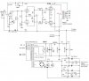
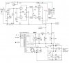
 
Power output specs weren't standardized prior to the FTC's involvement. A reasonable number for comparison purposes might be taken from 1KHz RMS voltage across the dummy load with clipping just visible on a scope: P = V^2 / R. Drive both channels if you want a more conservative number, or find the worst case over 20Hz ~ 20KHz if you're obsessive about it.

I think you've done some good work here. Good enough that lot of folks would appreciate having a complete schematic with operating voltages and major part numbers. You might even appreciate it yourself at some point in the future!
 
I use my regular RMS voltmeter connected to the output, and take that voltage, square it, and divide by 8 (the impedance of my dummy load) to get RMS power output. Need a voltmeter that doesn't lie at higher frequencies though, many do.


My scope doesn't have direct readout, so I just skip counting graticles and then doing math to convert it to RMS volts. Probably introduces more error than its worth. Scopes that don't rely on hoping they are still accurate after some 40 years, the Chinese probes having a true x10 attenuation, and me counting and doing the math properly might be less unreasonable to use.

I have an amp with the same basic front end, driving 7355 tubes. A 7355 is extremely comparable to a 5881 or a 6L6GB. Its a nice performing setup. Mine uses a 12AU7 for the voltage amp and a 12AX7 for the inverter though.
 
Hi BinaryMike You motivated me to finish the schematic I put on amp on the "finished" shelf yesterday and I was going to haul it back to the auto shop and put it back in service. Here is the schematic in all of its glory (just kidding) I know the driver 400v power supply isn't ideal and another rc filter would be nice but it's what I had on hand and I needed all the voltage I could give it. I will hook it back up to the scope tomorrow after work and take some pictures of the amp output on the scope screen and of the amp itself.

Gadget Thanks for the input. I have a nice handheld meter but I don't think it's true RMS. I think I will have to look in to one now.
fixed bias 6sl7 6sn7 6L6PP.jpg
 
Let me try to attach just the file.
fixed bias 6sl7 6sn7 6L6PP.jpg

Guess they do the same thing and you can see them about the same.

Gadget also if you would like the share the details of your amp I would enjoy hearing about it. Do you have a build thread on AK?
 
If you're feeding it a sine wave you probably don't need a true RMS meter, it just needs to be accurate at frequency. My handheld isn't by enough to make measurements not work right. If your scope will give you RMS voltage, thats probably plenty good enough. I just use the tools I have available.

Its not anything I built, its a Bogen DS-225. Bit of an odd duck, very unusual dual rectifier power supply with cathode feedback windings on the output transformers. It sounds great, but its unusual enough that it would be hard to clone it.
 
I turn it up to clipping on the scope, then back it off a hair. Measure output voltage with VTVM and calculate power output using ohms law. My DMM rolls off way too early to be useful unless I measure Power at 60hz
 
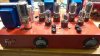
Good call on the VTVM. I tried that tonight and it did give me similar results as what my o scope said. But it was fun to watch and it did show 21 watts with one channel running but then it dropped down due to power supply sag. Here are some pictures of the ampWP_20170130_16_59_01_Pro.jpg View attachment 860357
 

Attachments

  • WP_20170130_16_58_53_Pro.jpg
    WP_20170130_16_58_53_Pro.jpg
    90.3 KB · Views: 0
Whats your plate voltage do under load? I'd honestly expect closer to 20 watts. I'd specifically be looking at what the screen supply does. I've got something with 6L6 tubes and the screens draw a pretty good amount of current, plenty enough to cause the voltage after a 33k resistor to tank. Maybe its time to consider active screen regulation to keep it from dumping so much.
 
Hi Gadget,
Yea the plate voltages sags around 20 volts but the screens sag around 36 volts. I did plug in the amp in to my main system in the living room and listened to it. It wasn't bad but I think the Gnfb needs a little tweaking as it sounded like it was lacking bass so I will work on that tonight. I will have to do a 20-20k sweep again to double check the frequency response.

Back to the screen regulation. I have some Bogens DB125 that are on the "to do" shelf (have tubes, caps, schematic but no time right now). They need a full recap and the usual restoration stuff. I know they have screen regulation but it's at 320volts so changing restor values would be a must but I have no idea what to change. Also I wonder how much current that 6cm7 can regulate. 6L6 tube data sheet says 12ma of grid current at max output per pair. So I need at least 24ma of current. I did some quick research on AK for screen regulators and saw a few with tubes and some with not. I did see Dave's EFB(tm) Screen Grid Regulator circuit but I haven't seen it in use it for 6l6's

Here is the link. http://audiokarma.org/forums/index.php?threads/efb-circuit-in-hh-scott-lk-48.717689/page-2

Wonder if I could make that work:idea: Otherwise I am open to tube and non-tube suggestions. Simpler the system the better it is for me. I have plenty of heater current and some room left in that amp.

Now I know why so many people like to use ultra linear configurations. You don't have to worry about screen supplies. :)
 
The EFB would do the trick. All you'd have to do is tweak the values, to get the screen voltage you want.

Otherwise- you could also use a gas regulator tube in series with the screens, one per channel, to drop 150v. A VR150./0C3 with a 470 ohm resistor in series (for stability) and a cap after that, would drop 150v at very low impedance, and one regulator tube can easily handle one pair of output tube screens (so it would take two regulators). I would put screen stopper/stability resistors on each screen (something like 220 ohm should be fine). If you did that, just separate the screen supplies from the B+ to the front end (split the B+ to the two regulators, and to the RC stage for the front end), so that they will be decoupled from each other.

IME, that will drop less than 5 volts on the screens, at full power. I did that on a 6L6 PP amp using some Scott output transformers, and got VERY good results.

Regards,
Gordon.
 
Back
Top Bottom