• The move to the new server is done. There are some software and database maintenance updates in process. This has us passing the hat around to help out. We appreciate any donations. Seriously, even a dollar helps. The payment page may be found here - https://www.audiokarma.org/support.html

Output rating on Tube Data Sheets RCA 6L6

EFB would be a much neater solution nowadays. The fact that Bogen was even bothering with screen regulation back then was pretty much unheard of.
 
I do like the idea of a gas regulator tube. Easy, 1 resistor but... I dug in my stash and I have zero gas regulator tubes. So looks like I will have to purchase a few if I want to go this route. I do like the idea of glowing tubes. Ha I might want to keep this one inside and put a different amp in the garage.

As for the EFB II
I am looking throught quite a few posts on AK about EFB II I found a few where there is modification to a fisher integrated/ http://audiokarma.org/forums/index.php?threads/improving-the-fisher-sa-100-with-efb-ii.476431/page-2 I saw the schematic but I couldn't find an explanation of how the resistor values were determined for it since the values will change since my voltages are different. If you guys have seen the explanation please let me know.
Thanks.
Mike.
 
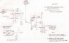
Its actually not as mysterious as it might seem. The 91K and the 270K resistor form a voltage divider. If you do the math on it, what the MOSFET is seeing at the junction of the 91K and the 270K is the difference in voltage between the input and what the screens feed. Basically you just need to pick a pair of resistors that will give you 250 volts at their junction to feed into the regulator. Total current across the resistors can be fairly low, 1-2ma is plenty. Higher also works but its a load on the supply for no reason. Handily, this will double as a filter cap bleeder network so they drain down when you shut it off. The other parts you can just use Dave's values for.

The bias part you should also be able to clone as drawn if you'd like.
 
This is the newest schematic I could find. There might be a newer one out there but I looked for quite a while and found this and a older schematic. I can move around values for a voltage divider, not a big deal. Next problem. I couldn't find STF10NK50Z mosfet or the older FQP9N506 from Newark or Allied and Allied doesn't sell Fairchild. I know next to nothing about plastic things with 3 legs so I don't know what is available with similar specs or what specs I have to look for. Thanks.
Mike.upload_2017-2-1_10-16-27.png
 
Let me try to attach just the file.
View attachment 859966

Guess they do the same thing and you can see them about the same.
Hi 6L6 , it might be that your in your amp's circuit it is exceeding the maximum grid resistance for the 6L6. Which for using fixed bias is less than 100K. Your grid resistor is already 100k according to the schematic.
 
Primosounds, What do you think would be the minimum value for the grid resistors I could use before the driver would be loaded down that I couldn't get the 40volts p-p needed to drive the output stage to the max? Right now I can just get 40 p-p

Mike.
 
The RCA 6L6G, 6L6GB and 6L6GC datasheets all say 100K (0.1 megohm) max for fixed bias. I'd leave it at that.
 
Back
Top Bottom