


You are using an out of date browser. It may not display this or other websites correctly.
You should upgrade or use an alternative browser.
You should upgrade or use an alternative browser.
PA1002A workaround / replacement
- Thread starter Bob@FM
- Start date

Bassblaster
Super Member
UPDATE
I Haven't been on a lot lately due to my busy work schedule. I Have been out of PCB's for a good while now. The schematic and Gerber is up on my EasyEDA page. All people have been credited
https://easyeda.com/bassblaster505/Pioneer-PA1002A
From there you can order them from JLCPCB, which is the same company.
I Haven't been on a lot lately due to my busy work schedule. I Have been out of PCB's for a good while now. The schematic and Gerber is up on my EasyEDA page. All people have been credited
https://easyeda.com/bassblaster505/Pioneer-PA1002A
From there you can order them from JLCPCB, which is the same company.
Last edited:
Super Noob
Super Member
Installed. Working.
1280 FM = Alive.
Thanks to @Bassblaster @rcs16 @Bob@FM
Have a pile of the these boards - so PM if you need one.


1280 FM = Alive.
Thanks to @Bassblaster @rcs16 @Bob@FM
Have a pile of the these boards - so PM if you need one.

Oldsansui441
Super Member
Nice work Super Noob  .
.
.
Bob@FM
Well-Known Member
Nice work Super Noob
Really glad to see this project is still alive and helping folks keep the Pioneer units playing.
Bob

Xeon Helton
New Member
Yes indeed SuperNoob ! thank you so much for the workaround pcb you graciously sent .. you are my hero my friend !
edit: and im going to carry the torch to keep it alive via the design and boards made available for us, so nobody has to endure that sinking feeling of having an 80 series and others like it and being faced with an unobtanium PA1002 part. and with this workaround, follks can get their FM working again in their beloved old school silver face gear !


thanks goes to the great folks i mention below that were involved in creating this fix ! ----- if i left out anyone pm me and ill add you
@Supernoob @Bassblaster @rcs16 @Bob@FM
edit: and im going to carry the torch to keep it alive via the design and boards made available for us, so nobody has to endure that sinking feeling of having an 80 series and others like it and being faced with an unobtanium PA1002 part. and with this workaround, follks can get their FM working again in their beloved old school silver face gear !
thanks goes to the great folks i mention below that were involved in creating this fix ! ----- if i left out anyone pm me and ill add you
@Supernoob @Bassblaster @rcs16 @Bob@FM
Last edited:
Xeon Helton
New Member
I got 40 boards being made at jlpcb so when i get them i will post here letting folks know. there will be no charge but limit 1 per hobbyist.. paying it forward like supernoob did for me
i chose 20 yellow and 20 blue boards just for variety
and all credit goes to: @Supernoob @Bassblaster @rcs16 @Bob@FM
bom is attached here below- mouser part numbers- "open with wordpad or word"
i chose 20 yellow and 20 blue boards just for variety
and all credit goes to: @Supernoob @Bassblaster @rcs16 @Bob@FM
bom is attached here below- mouser part numbers- "open with wordpad or word"
Attachments
Last edited:
Bob@FM
Well-Known Member
If you use machine pin sockets, you may find the headers with round pins fit easier than headers with square pins.
Also that you should insert both rows of header pins into the machine pin socket before soldering to the adapter board. Doing it this way makes sure the alignment is correct between the socket and pins.
Bob
Also that you should insert both rows of header pins into the machine pin socket before soldering to the adapter board. Doing it this way makes sure the alignment is correct between the socket and pins.
Bob
Xeon Helton
New Member
If you use machine pin sockets, you may find the headers with round pins fit easier than headers with square pins.
Also that you should insert both rows of header pins into the machine pin socket before soldering to the adapter board. Doing it this way makes sure the alignment is correct between the socket and pins.
Bob
i highly recommend what Bob says here. just get the machine pin sockets and not those standard sockets.. they grab all the way around instead of just one side of the pins... the ones in bom parts list are the machine pin types
Bassblaster
Super Member
Machine pin is definitely the way to goi highly recommend what Bob says here. just get the machine pin sockets and not those standard sockets.. they grab all the way around instead of just one side of the pins... the ones in bom parts list are the machine pin types
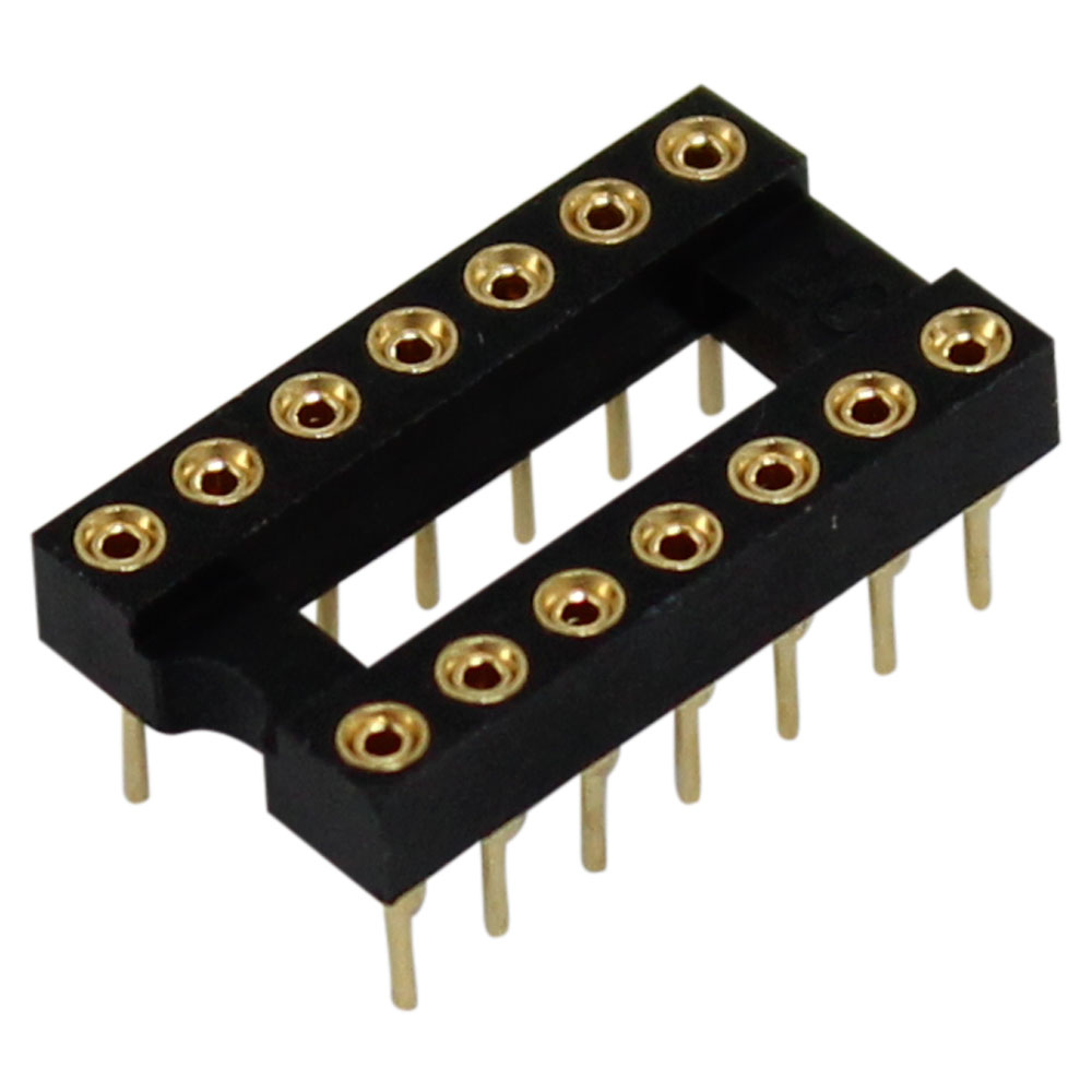
Regular cheaper "eBay special" DIP sockets for reference


OK, so I have a couple questions about assembly. First of all, the old chip has 16 pins, and the headers have 16 pins total, but the socket is only 14 pin. Are you just not using two of them?
Second, I had some difficulty with the 14 pin socket. I tried to push the header into it, but was unable to. Do you really just have to jam it in there? Are there headers with thinner pins available?
On a related note, I had some difficulty pushing the header directly into the circuit board, though I was able to eventually. Again, are there headers with thinner pins, or do you just have to put some effort into it?
Finally, do we know what’s causing these chips to die? I am guessing it is bad tantalum or other electrolytic caps on the board. One of the caps right next to the chip was testing about three times higher than it was supposed to.
Second, I had some difficulty with the 14 pin socket. I tried to push the header into it, but was unable to. Do you really just have to jam it in there? Are there headers with thinner pins available?
On a related note, I had some difficulty pushing the header directly into the circuit board, though I was able to eventually. Again, are there headers with thinner pins, or do you just have to put some effort into it?
Finally, do we know what’s causing these chips to die? I am guessing it is bad tantalum or other electrolytic caps on the board. One of the caps right next to the chip was testing about three times higher than it was supposed to.

Where did you get the idea that a 14 pin socket was somehow involved?
The parts list from Mouser includes a 14-pin socket.
https://www.mouser.com/ProjectManager/ProjectDetail.aspx?AccessID=4ea6de02c1
https://www.mouser.com/ProjectManager/ProjectDetail.aspx?AccessID=4ea6de02c1
Bassblaster
Super Member
Whoa whoa whoa I never caught that. That will be fixed ASAPThe parts list from Mouser includes a 14-pin socket.
https://www.mouser.com/ProjectManager/ProjectDetail.aspx?AccessID=4ea6de02c1
EDIT: won't be able to fix it for a few more hours who would have known that Mousers shitty mobile app doesn't allow me to sign into my account to modify projects so I'll have to wait till I get home and get on my computer.
Last edited:

Kingbleu
Well-Known Member
Doh I ordered the 14-pin socket. Scratching my head, I came back to read the last few posts here. I was excited to get this chip installed. Repair delayed.The parts list from Mouser includes a 14-pin socket.
https://www.mouser.com/ProjectManager/ProjectDetail.aspx?AccessID=4ea6de02c1
Bassblaster
Super Member
MOUSER BOM HAS BEEN FIXED AND UPDATED!!Whoa whoa whoa I never caught that. That will be fixed ASAP
EDIT: won't be able to fix it for a few more hours who would have known that Mousers shitty mobile app doesn't allow me to sign into my account to modify projects so I'll have to wait till I get home and get on my computer.
- Both 16 and 8 Pin Dip sockets are Mill-Max 0110 Series, Tin Plated that accepts .015” - .025” diameter and standard IC leads.
16 Pin DIP
Manufacture Part Number: 110-44-316-41-001000
Mouser Part Number: 575-11044316
Digi-Key Part Number: ED90050-ND
8 Pin DIP
Manufacture Part Number: 110-41-308-41-001000
Mouser Part Number: 575-11041308410010
Digi-Key Part Number: ED90515-ND
IF YOU WANT GOLD PLATED DIP SOCKETS
16 Pin DIP
Manufacture Part Number: 110-13-316-41-001000
Mouser Part Number: 575-113316
Digi-Key Part Number ED56163-ND
8 Pin DIP
Manufacture Part Number: 110-13-308-41-001000
Mouser Part Number: 575-113308
Digi-Key Part Number: ED56083-ND
- The pin headers to connect the PA Board to the DIP16 socket are Molex 42375 Series, Tin Plated.
8 Pin SIP
Manufacture Part Number: 22-28-4080
Mouser Part Number: 538-22-28-4080
Digi-Key Part Number: WM50014-08-ND
IF YOU WANT GOLD PLATED PIN HEADERS
8 Pin SIP
Manufacture Part Number: 22-28-4083
Mouser Part Number: 538-22-28-4083
Digi-Key Part Number: WM50016-08-ND
Last edited:
Xeon Helton
New Member
ok guys, sorry for the delay in responding but the boards will be here soon.. they are finished and being shipped.. i have blue or yellow. send me a dm if you want one free of charge but only one per member. i got 40.. and a good day to you good folks ! Harris
Kingbleu
Well-Known Member
I couldn't wait for the 16-pin socket, so I bored out the holes on the tuner circuit board with a pin vise. Got it installed nicely but that didn't fix my problem. Continuing the shotgun approach I ordered three transistors
Q1 3Sk45 from ebay supposedly New Old Stock
Q2 and Q3 2SC535. NTE equivalent NTE 108
Q1 3Sk45 from ebay supposedly New Old Stock
Q2 and Q3 2SC535. NTE equivalent NTE 108
FM front end.... Might be more appropriate to start a new thread? 
I reread your portion in this thread, I think that the tuner needs an alignment (badly)
Not sensitivity peaking, the pa3001 settings. T6 and all that.
First, on a no signal condition, you need to dial in the 10.7 MHz - step 8 in the tuner instructions.
What FM signal generator do you have (you mentioned 400 Hz)
p.s. In the Chicago market, I have a heck of a time setting that, having to take extraordinary measures to get dead air in THAT packed spectrum.
I reread your portion in this thread, I think that the tuner needs an alignment (badly)
Not sensitivity peaking, the pa3001 settings. T6 and all that.
First, on a no signal condition, you need to dial in the 10.7 MHz - step 8 in the tuner instructions.
What FM signal generator do you have (you mentioned 400 Hz)
p.s. In the Chicago market, I have a heck of a time setting that, having to take extraordinary measures to get dead air in THAT packed spectrum.
Last edited: