


You are using an out of date browser. It may not display this or other websites correctly.
You should upgrade or use an alternative browser.
You should upgrade or use an alternative browser.
PA1002A workaround / replacement
- Thread starter Bob@FM
- Start date

Xeon Helton
New Member
i have the work around PA1002a blank boards. 1 free per member until gone -- ive got 40 -- white or blue pm me your info and color if prefered and ill send you one.. my thanks to you all for helping me and everyone else out ! regards, Harris
this is for the unobtanium workaround for the pa1002a

this is for the unobtanium workaround for the pa1002a
Last edited:

ATTENTION!!!!!!!
I just saw this on Ebay.
https://www.ebay.com/itm/294534581540?hash=item4493a10d24:g:ZIIAAOSwGf9g9vFm
I purchased a couple myself for stock.
I just saw this on Ebay.
https://www.ebay.com/itm/294534581540?hash=item4493a10d24:g:ZIIAAOSwGf9g9vFm
I purchased a couple myself for stock.
Last edited:
Hi AE Bob! I saw those too and (finally) registered on this awesome web page to see if anyone else had experience with these. I am going to order a couple for stock...I have more money than brains (subject to what the stock market does today...) and I will buy a couple also. Hopefully they are legit.ATTENTION!!!!!!!
I just saw this on Ebay.
https://www.ebay.com/itm/294534581540?hash=item4493a10d24:g:ZIIAAOSwGf9g9vFm
I purchased a couple myself for stock.

Hopefully they are legit.
I've dealt with this seller for years and has always been standup and trustworthy. Ordered a few for stock myself.
Yes, the seller ceitron is Consolidated Electronics Inc. in Ohio. Steve was one of the principles of MCM Electronics. I have NEVER had an issue with any product from Consolidated Elec.
Thank you for sounding off. That is great to hear. Hearing your voice of confidence and the history behind this guy makes me feel awesome. In today’s environment of anonymity and a crook around every corner, it’s hard to know what to do and sometimes I just throw my line in the water to see what happens and I rely on the goodness of others.
Once this guy gets more press, people will probably buy his chips by the handful “just in case”. Then, when we pass, our descendants will come across bags of “these bug like things” and probably throw them away.
I live in the Seattle area. There are a couple of guys out here who are super cool and do great repairs on old pioneer equipment. One of them is 73 and can fix anything. The problem is he gives all his advice for free and neither one of them charges enough! He should charge people just to hang out in his shop and listen to his stories. I feel fortunate to be able to know these masters of their craft.
Anyway, I will look forward to getting my chips and stashing them away hopefully never to use them.
PS, I have two SX-1280s which I bought off of eBay in 2000 and a SX-939 which my dad bought new and just gave to me.
I can post a schematic of my muting add on to the work around PC board. The only issues not yet complete yet are the R and C values for the turn on timing delay, as I have been experimenting with different values, and delays. The current prototype is just built up in "spider Web" construction. I can include a photo but I don't think it will help much (it's rather a mess)
My mute design simply takes the outputs to ground, through an optically switched solid state FET relay, controlled by another FET from the stock tuner mute signal. It can be added anywhere before the output phono jacks. I tested the unit with no muting for both turn on and turn off pops, and heard none (that were very loud), so did not worry about that. This is still untested. I have a couple different relays here I wanted to test. I wanted to do a universal design I could use for other projects, like outboard MPX decoders and home made preamps.
I have been testing the work around in a Pioneer TX-7800 Tuner, so the turn on and turn off pops are very apparent in the connected amp. In a Pioneer Receiver, I don't think they will show up because the protection relay is open when the turn on pop occurs, and I suspect the protect relay opens again before the +13 volts drops causing the turn off pop. In the tuner there is nothing to stop the pop from reaching the amplifier. The design I am working on is an addition to the "Work Around" PC board, so it will be "Plug and Play" for the PA1002A (no additional connections). I have the normal inter station mute working properly, the turn on pop issue figured out (still working on ideal timing values), and I still need to design some circuitry to take care of the turn off pop.
OK, it makes sense to do a new design / board with it all on there. I hope figuring out the rail splitter / op-amp stuff helped a little.
I don't have big speakers hooked up in my lab, so how apparent the low end pop is can be relative. Most guys know to turn the volume down anyways, I am hoping? Switching things on and off in with the volume cranked up is never something I recommend to anyone, but shirt happens.
Hi,
I'm wondering what the status of the workaround board with muting is.
I would like to use a modern opamp in my TX-9500II but would like to keep the muting alive.
Thanks!

Bob@FM
Well-Known Member
The muting is on the back burner for now. I would suggest trying it without muting, and see if you really need it.
I may do the mute board if I need it for another preamp project though, later this winter.
The mute board I dreamed up is universal design, that uses solid state switches to shunt the signal to ground. In the TX-9500 II this little board would need to be added on in another place, at the board edge, to short the L and R outputs to gnd.
It's a simple design, most of the work is in selecting the parts and laying out the board. You need to get a mute signal from somewhere, though, and the first PA1002A replacement board has an output pin for that. I prefer to shunt to gnd versus switching the signal. If you want to continue to it and do the board, I'll give you the details.
Bob
I may do the mute board if I need it for another preamp project though, later this winter.
The mute board I dreamed up is universal design, that uses solid state switches to shunt the signal to ground. In the TX-9500 II this little board would need to be added on in another place, at the board edge, to short the L and R outputs to gnd.
It's a simple design, most of the work is in selecting the parts and laying out the board. You need to get a mute signal from somewhere, though, and the first PA1002A replacement board has an output pin for that. I prefer to shunt to gnd versus switching the signal. If you want to continue to it and do the board, I'll give you the details.
Bob
The muting is on the back burner for now. I would suggest trying it without muting, and see if you really need it.
I may do the mute board if I need it for another preamp project though, later this winter.
The mute board I dreamed up is universal design, that uses solid state switches to shunt the signal to ground. In the TX-9500 II this little board would need to be added on in another place, at the board edge, to short the L and R outputs to gnd.
It's a simple design, most of the work is in selecting the parts and laying out the board. You need to get a mute signal from somewhere, though, and the first PA1002A replacement board has an output pin for that. I prefer to shunt to gnd versus switching the signal. If you want to continue to it and do the board, I'll give you the details.
Bob
Thank you Bob.
I actually do have the parts ordered to try the current version without muting.
--Mark--
Bob@FM
Well-Known Member
If you use a socket on the tuner board, the best header to use will be a round pin type. A square pin header will not fit the socket. Here's the best series I could find at Mouser -
https://www.mouser.com/datasheet/2/527/bbl-2853990.pdf
If you want gold, here is the link to a 16 pin gold low profile header BBL-116-G-E. You need one of these per PA1002A board.
https://www.mouser.com/ProductDetail/Samtec/BBL-116-G-E?qs=0lQeLiL1qyYBjeV%2BmG2/Rw==
Bob
https://www.mouser.com/datasheet/2/527/bbl-2853990.pdf
If you want gold, here is the link to a 16 pin gold low profile header BBL-116-G-E. You need one of these per PA1002A board.
https://www.mouser.com/ProductDetail/Samtec/BBL-116-G-E?qs=0lQeLiL1qyYBjeV%2BmG2/Rw==
Bob

Bassblaster
Super Member
Long time no posts, After a big "clean my workbench" night I found I still have a few PCBs left if anyone is still needing one or 2.


Bassblaster
Super Member
I have 2Hi,
I'm trying to help a friend of mine about a faulty TX-8500 II. Even in that case, the infamous PA1002A is faulty.
Any remaining PCB available?
Thx a lot in advance to everyone


not0815
New Member
Hello,
I stumbled across this thread by chance while looking for a replacement for the PA1002a (for the Pioneer SX-980). The solution shown here unfortunately omits the muting function. I'm therefore wondering if it's possible to add it. I came up with the following idea:
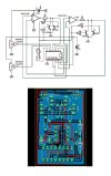
The small circuit board should stand vertically be connected using right-angle connectors.
Would it still work with the muting function this way?
Greetings
Sven
P.S. Sorry for the poor English.
I stumbled across this thread by chance while looking for a replacement for the PA1002a (for the Pioneer SX-980). The solution shown here unfortunately omits the muting function. I'm therefore wondering if it's possible to add it. I came up with the following idea:
The small circuit board should stand vertically be connected using right-angle connectors.
Would it still work with the muting function this way?
Greetings
Sven
P.S. Sorry for the poor English.
Last edited:

Tkhater
Active Member
I don’t think this is going to work. Maybe someone can correct me if I am wrong but muted voltage will be at the rail splitter (virtual ground) voltage. If you use real ground to ground out your signal, you will essentially be running the amp at full negative DC. Also, you will need to separate out the NFB pin from the muted output pin. Basically the op amp output needs to go to pin 4 and 13, then your muting circuit needs to be put in and that output needs to go to 5 and 12. If you just mute 4 and 13 the op amp may do weird stuff and cause a strange output pop or something when triggering an unmuted state.
Perhaps you can find a mux chip that will switch your pin 5/12 outputs between opamp out voltage and rail splitter voltage?
Thanks for the efforts!!!!
Perhaps you can find a mux chip that will switch your pin 5/12 outputs between opamp out voltage and rail splitter voltage?
Thanks for the efforts!!!!