• The move to the new server is done. There are some software and database maintenance updates in process. This has us passing the hat around to help out. We appreciate any donations. Seriously, even a dollar helps. The payment page may be found here - https://www.audiokarma.org/support.html

Parallel Resistive Loading

Ive been curious aboot loading, this idea of using the Y-splitter is right up my alley. Now to put my maths to the test.

 
Ive been curious aboot loading, this idea of using the Y-splitter is right up my alley. Now to put my maths to the test.

Did you read the posts near the beginning of the the thread, one of the cartridge that benefited is the Shure M97xE.

A very nice cartridge that turned great with a little bit of help. :thumbsup:
 
Carbon based resistors can exhibit very high levels of thermal noise.
I think carbon resitors can add thermal noise in series. But these are parrallel.....which reduces thermal(s).
I know these are very old comments but I'll respond anyway since this thread has been resurrected.
Yes, carbon resistors are noisy, but it isn't thermal noise. Thermal noise, also known as Johnson noise, is inevitable in any resistor and is temperature dependent, hence its name.
https://en.wikipedia.org/wiki/Johnson–Nyquist_noise
Carbon resistors produce noise in addition to thermal noise and it's known as excess noise.
Still, the advice to avoid carbon resistors is good. Metal films are much better and don't cost a lot of money.
 
FWIW my loading box is still in permanent use here and this is easy to check - a flick of a button engages and disengages the parallel load consisting of a carbon resistor and adjustable potentiometer in series.

Absolutely no audible difference in or out (other than tonal tuning)

Photo%2013-01-2019%2C%206%2049%2054%20pm.jpg
 
Now what if you want to add Parallel capacitance loading with Y connectors? Do you have to daisy chain them together?

Nashou
 
Curious to hear if anyone has tried the DB Systems resistive loading kit.
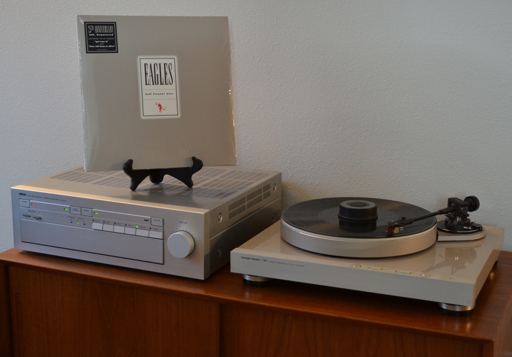
I am - sort of....

I picked up a used kit from a local craigslist seller yesterday. It's the DPB-6MC kit mentioned elsewhere in this thread. Obviously, made for moving coil cartridges, which I don't have. I just got my Grado G2+ twin tip stylus back from @marcmorin, cleaned, inspected and tested, and Marc recommended loading it at 22 - 24K ohms. My amp (Yamaha A-1000) has the standard 47K input for MM carts, so I needed some parallel loading plugs and Y-splitters to drop the resistive loading into the desired range.

I was originally planning to make my own, but this kit has been listed for a while on my local craigslist, I called up the seller, made him an offer and he accepted it. I swung by my local Fry's and picked up some 1/2 watt 47K ohm metal film resistors, soldered them in one set of the plugs and am listening to it now:

Hell-Freezes-Over-3.jpg


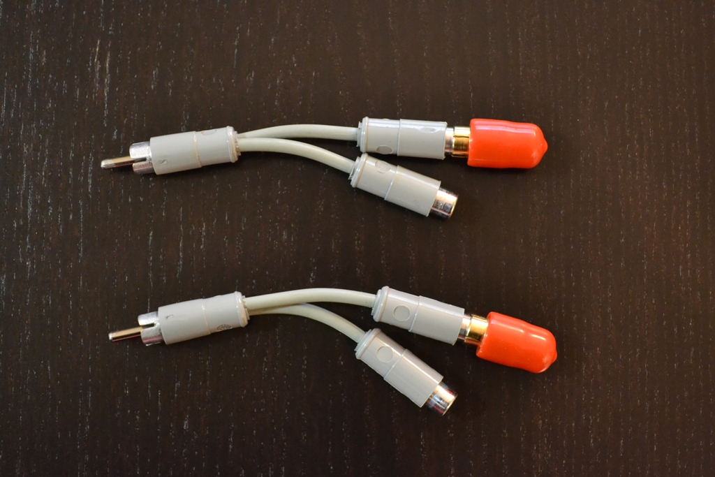
Form the outside, it looks like the standard DB Systems DBP-6MC kit:

DB-Systems-Resistive-Loading-Kit-1.jpg


The only difference was soldering the 1/2 watt metal film 47K ohm resistors, which results in 23.5K ohm total resistance, in place of the original 1/4 watt carbon 20 ohm (no "K") resistors. I also have four more sets of plugs I can play around with in the future. Total cost for the (used) kit + 47K resistors = $16.49. The only drawback is under the color coded slip on caps are some hard black plastic threaded caps that screw onto the RCA plugs. DB Systems chose to glue these threaded black plastics caps in place. That makes dissembling them and changing the resistors a pain (no doubt intentional). I've managed to break a few of them free, but still have more to go.
 
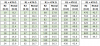
For anyone contemplating making their own parallel resistance plugs, I created the following tables based on the E24 decade table of standard resistor values:

upload_2019-4-9_16-46-20.png

These tables assume a phono preamp with the (somewhat) standard input resistance of 47K Ohms.

As mentioned previously, the formula for parallel resistance is: Rtotal = 1/(1/R1 +1/R2). Easy enough, but these tables will save you opening a calculator and punching in some numbers.

For example, if you desire an input resistance of 32K Ohms, you would use 100K Ohm resistors in your DIY plugs.
 
Now what if you want to add Parallel capacitance loading with Y connectors? Do you have to daisy chain them together?

Nashou

A bit late to the discussion, but, yes, I have experimented with adding capacitance (100pf to 700pf) in about 100pf increments. I do this on the secondary side of my SUTs before my phono preamp for my MC carts. The goal is to address a perceived peak in higher frequencies versus doing so with resistors. The impact of the capacitors in this situation seems to me to be more subtle than when using resistors and I'm not sure what the capacitors are doing to the response curve. It does not appear to me that increasing the capacitance always reduces the perceived peak but may be moving it around in the range I can hear. I don't have test equipment to see what is going on so it is hit or miss. A couple SUT makers (Sowter and Jensen) show Zobel networks (resistance and capacitance) on the output side of their transformers but that is way beyond my skill set.

For MM cartridges what you describe would seem an easy approach to loading. Just add up the capacitance of the cables and preamp versus what is recommended for the cartridge and then adjust by adding capacitance to taste. Low capacitance cables provide the latitude to add what is needed.
 
The impact of the capacitors in this situation seems to me to be more subtle than when using resistors and I'm not sure what the capacitors are doing to the response curve.

Seems like resistor loading is also very subtle (although it would depend on the cart and setup). Recently, I did some tests with loading resistors for a DV XX2mk2 into an SUT into the MM inputs on a phono pre. Loading was done on the SUT side. Before this, I had already settled on about 80 ohms for this cart based on my subjective listening tests - not shrill and with sufficient detail and sold bass. I had some resistors lying around to do tests at about 200 Ohms (e.g., no loading resistors and the SUT at 1:15x), 125 Ohms (using a 68K resistor), 100 Ohms (using a 47K resistor), and 80 Ohms (using a 30K resistor). The test results are below - fairly subtle changes in HF dB levels with resistors but I still preferred loading at 80 Ohms. The cart may need some more fine tuning, but it is good to see what works via listening tests confirmed via data.

200 Ohms:
index.php


125 Ohms:
index.php


100 Ohms:
index.php


80 Ohms:
index.php
 
Last edited:
@edwyun: Thanks for posting your results of various resistor loadings of your DV cart. I assume you are loading the secondary side of the SUT, correct?

The graphs are terrific but I can't blow them up enough to be able to read the vertical axis but I assume it is db and the horizontal is frequency. Is there a greater db at the higher frequencies? Where does it start and how did the resistor loading tame it, or not. Every try a some capacitors or a Zobel Network on the secondary side of the SUT?
 
@AvFan:

Yes, loading on the secondary side of the SUT (though it would be better I think to select the proper resistor in the phono pre, which I am loathe to do).

Here's a larger version of the 80 Ohms results, dBFS vs Hz. The loading reduced the slight peak at 16kHz to a more manageable level (3.39dB down to 2.77dB on the left, and 2.57dB down to 1.81dB on the right, maybe with more adjustment of the cart it could be better). As for adding on the secondary side, I try to keep it simple to the extent possible.
 

Attachments

  • 81 ohms large.jpg
    81 ohms large.jpg
    60.7 KB · Views: 10
Last edited:
If a source impedance is purely resistive the only effect that a change of load impedance would have is to alter the signal level. However, feeding a purely resistive source into a typical step-up transformer and changing the load impedance on the secondary side of the transformer will affect the response, not because the source is load-sensitive but because the transformer is load-sensitive. Conducting tests like these and drawing conclusions about the cartridge's performance based on the load impedance the cartridge sees can be misleading. Is the change in performance due to the load on the cartridge or the load on the transformer? What is the load on the cartridge anyway? It may seem logical that a 30k load on the secondary in addition to the 47k load of the phonostage results in an 80 ohm load on the cartridge, but in reality the load will appear to be much more like a capacitor at high frequencies. Concluding that a particular cartridge is optimised by a particular load impedance based on this type of test would be a mistake in my opinion.
Of course, it would make sense to treat the cartridge and transformer as an integrated system and fine tune the performance that way, and in that sense these tests are valid. Just be wary about drawing universally applicable conclusions from them.
 
If a source impedance is purely resistive the only effect that a change of load impedance would have is to alter the signal level. However, feeding a purely resistive source into a typical step-up transformer and changing the load impedance on the secondary side of the transformer will affect the response, not because the source is load-sensitive but because the transformer is load-sensitive. Conducting tests like these and drawing conclusions about the cartridge's performance based on the load impedance the cartridge sees can be misleading. Is the change in performance due to the load on the cartridge or the load on the transformer? What is the load on the cartridge anyway? It may seem logical that a 30k load on the secondary in addition to the 47k load of the phonostage results in an 80 ohm load on the cartridge, but in reality the load will appear to be much more like a capacitor at high frequencies. Concluding that a particular cartridge is optimised by a particular load impedance based on this type of test would be a mistake in my opinion.
Of course, it would make sense to treat the cartridge and transformer as an integrated system and fine tune the performance that way, and in that sense these tests are valid. Just be wary about drawing universally applicable conclusions from them.
Rothwell is entirely right in this. I model my MC cartridge/pickup arm/SUT/preamp extensively and getting a good match to the actual frequency response and how it behaves as load is changed is quite tricky.
Below is a SIMPLIFIED model of such a system, just to show how complex it is. Caveat emptor...

mod.PNG
 
Back
Top Bottom