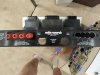
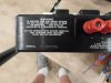
I was originally thinking of using names like Humpty Dumpty or The Phoenix in the title of this thread. But as will be seen, they don't fully describe the full context of the project, although large elements of those names certainly apply. Humpty Dumpty implies attempting to put something back together again that was originally together in the first place -- which isn't exactly true in this case. The Phoenix implies building something new out of old ashes -- but the parts and pieces that make up this project are hardly ashes (in fact, many are new). And yet, the project very much involves putting something together that is quite complex (Humpty Dumpty), and new (The Phoenix), from well -- as I came to find out -- parts and pieces from........somewhere. And so the title of the thread as given came to be.
1983 -- By this time, ARC was already credited with single handedly saving the vacuum tube side of the high fidelity industry, when Bill Johnson and his fledgling little ARC company alone started producing very high quality, high performance vacuum tube amplifiers a decade earlier, filling the void created when McIntosh ceased production of their original tube amplifiers around 1970. But unlike Mac's well proven and elegant Unity Coupled design using a conventional if not simple power supply section, ARC went a different route, using a more conventional audio design, but with a highly complex power supply section.
With ARC's designs, a conventional OPT is employed, as is even the lowly balanced paraphase style phase inverter. Both Mac and ARC used cross-coupling to help enforce a balanced push-pull signal being presented to the output stage, although the ARC design is much more aggressive in this regard using active, dedicated, cross-coupled stages to accomplish it, rather than Mac's more passive approach by comparison. Mac and ARC both also used local push-pull feedback around the output stage as well. But here it was Mac who was much more aggressive with their Unity Coupled design, where as ARC's use of local push-pull feedback is far less impacting, using the loaded secondary output winding to supply the feedback. Both designs use direct coupling where possible with a bare minimum of coupling caps, with ARC using cap bundles for its coupling networks.
The one big difference in the audio section between Mac and ARC, is that Mac used a traditional single ended global feedback network, whereas ARC used a balanced, push-pull global feedback system. Theoretically, dB for dB, the ARC approach is more effective, which I hope to determine when all is said and done.
In the power supply section however, things couldn't be more different. The Mac approach is a picture of simplicity, using either a voltage doubler or full wave bridge rectifier, a choke, and conventional filtering and decoupling using electrolytic caps. ARC went down a very different and complex road, using massive electrolytic power supply capacitance at the output of the B+ rectifiers (1000's of uF), and then regulated the voltage to the output tube screen and control grids, and to all of the small signal stages as well. Significantly, the ARC approach does not use a single electrolytic cap to decouple any power supply point after the main filter caps at the rectifiers -- nor does it use exotic and large film caps in their place to accomplish that end, either. ARC uses the inherently low output impedance of its various regulators (a total of four discrete ones, plus a couple of 3T type regulators) to decouple the various small signal stages, so that no electrolytic caps are needed for that purpose. Back in the day, it was the height of the "no cap is the best cap" idea, and ARC ran with it to the max.
The ARC design then was no "me too" Mac imitator but rather, it's own uniquely different approach to producing high quality sound. The brand doesn't get a lot of chatter on AK for some rather obvious reasons (I believe), be it lower production numbers, higher that typical voltages, cost, and complexity to name a few. So with this project starting from basically less than square one, I thought it would make for an excellent opportunity to take a good look at, and document all that went into vintage ARC design and construction. With that then, on to the project itself.
It arrived on my doorstep via my good friend BuzzK who obtained it from a widow, whom along with her late husband, used to own a high end audio salon for many years in Arkansas. Besides both of them attending to the day to day operation of the store, she did the books, and he was the in-house repair for both Mac and ARC, whom they were authorized dealers for. Over the years then, she became quite knowledgeable of the various pieces of equipment they sold. When they retired, they moved to GA, bringing with them many of the pieces they retained when they closed up shop in Arkansas. Here in GA, they had sold off most of the pieces that were operationally ready to go, and were down to the items needing repair or restoration, which he was in the process of doing, when he unfortunately passed away. After a period of time, Buzz became aware that she was trying to sell off the remainder of the equipment (piece by piece), and that she was also very aware of the value of the equipment she had -- even in its compromised state. Buzz made a run to see her, which resulted (in part) in the purchase of my own very nice MC240 from her about 5 years ago, that ultimately needed only very minor attention to make it operational. Shortly after that, I then made my own run, which resulted in the purchase of my C11 preamp that needed a full restoration. Buzz had made one other run however that resulted (also in part) in the subject of this thread. Clearly being down to the crumbs of what was left, here's how it arrived here:

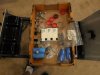
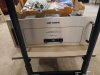
Now how cool is that!! An ARC D115 kit!! -- and already partially built, too!! Except, this was no kit. As I came to find out, it was in fact a real audio mystery, with my initial research indicating it had been in this state of hibernation for nearly two decades. Right away, there were things that simply didn't add up, so to make any serious progress on it then, the mystery had to first be unraveled so at least I knew what I was dealing with. For vintage ARC devotees, there are already a few clues to be seen that should raise some eyebrows. Short of determining that however, because of its condition, I only paid about 10 cents on the 1983 dollar it sold for, so at the very least, its hardly a boat anchor but a dolly full of great parts. I am determined to see it through however, so what it really is for me, is the ultimate 2020 Covid project. It's still far from being finished, moving along with slow but methodical progress. But it's well under way, with enough progress having been made now that a thread can be started.
How a unit comes to be in the state it's in when it arrives here always fascinates me. The mystery as to how this piece came to be as shown when it arrived here is deep, but will start to unravel -- next time.
Dave
1983 -- By this time, ARC was already credited with single handedly saving the vacuum tube side of the high fidelity industry, when Bill Johnson and his fledgling little ARC company alone started producing very high quality, high performance vacuum tube amplifiers a decade earlier, filling the void created when McIntosh ceased production of their original tube amplifiers around 1970. But unlike Mac's well proven and elegant Unity Coupled design using a conventional if not simple power supply section, ARC went a different route, using a more conventional audio design, but with a highly complex power supply section.
With ARC's designs, a conventional OPT is employed, as is even the lowly balanced paraphase style phase inverter. Both Mac and ARC used cross-coupling to help enforce a balanced push-pull signal being presented to the output stage, although the ARC design is much more aggressive in this regard using active, dedicated, cross-coupled stages to accomplish it, rather than Mac's more passive approach by comparison. Mac and ARC both also used local push-pull feedback around the output stage as well. But here it was Mac who was much more aggressive with their Unity Coupled design, where as ARC's use of local push-pull feedback is far less impacting, using the loaded secondary output winding to supply the feedback. Both designs use direct coupling where possible with a bare minimum of coupling caps, with ARC using cap bundles for its coupling networks.
The one big difference in the audio section between Mac and ARC, is that Mac used a traditional single ended global feedback network, whereas ARC used a balanced, push-pull global feedback system. Theoretically, dB for dB, the ARC approach is more effective, which I hope to determine when all is said and done.
In the power supply section however, things couldn't be more different. The Mac approach is a picture of simplicity, using either a voltage doubler or full wave bridge rectifier, a choke, and conventional filtering and decoupling using electrolytic caps. ARC went down a very different and complex road, using massive electrolytic power supply capacitance at the output of the B+ rectifiers (1000's of uF), and then regulated the voltage to the output tube screen and control grids, and to all of the small signal stages as well. Significantly, the ARC approach does not use a single electrolytic cap to decouple any power supply point after the main filter caps at the rectifiers -- nor does it use exotic and large film caps in their place to accomplish that end, either. ARC uses the inherently low output impedance of its various regulators (a total of four discrete ones, plus a couple of 3T type regulators) to decouple the various small signal stages, so that no electrolytic caps are needed for that purpose. Back in the day, it was the height of the "no cap is the best cap" idea, and ARC ran with it to the max.
The ARC design then was no "me too" Mac imitator but rather, it's own uniquely different approach to producing high quality sound. The brand doesn't get a lot of chatter on AK for some rather obvious reasons (I believe), be it lower production numbers, higher that typical voltages, cost, and complexity to name a few. So with this project starting from basically less than square one, I thought it would make for an excellent opportunity to take a good look at, and document all that went into vintage ARC design and construction. With that then, on to the project itself.
It arrived on my doorstep via my good friend BuzzK who obtained it from a widow, whom along with her late husband, used to own a high end audio salon for many years in Arkansas. Besides both of them attending to the day to day operation of the store, she did the books, and he was the in-house repair for both Mac and ARC, whom they were authorized dealers for. Over the years then, she became quite knowledgeable of the various pieces of equipment they sold. When they retired, they moved to GA, bringing with them many of the pieces they retained when they closed up shop in Arkansas. Here in GA, they had sold off most of the pieces that were operationally ready to go, and were down to the items needing repair or restoration, which he was in the process of doing, when he unfortunately passed away. After a period of time, Buzz became aware that she was trying to sell off the remainder of the equipment (piece by piece), and that she was also very aware of the value of the equipment she had -- even in its compromised state. Buzz made a run to see her, which resulted (in part) in the purchase of my own very nice MC240 from her about 5 years ago, that ultimately needed only very minor attention to make it operational. Shortly after that, I then made my own run, which resulted in the purchase of my C11 preamp that needed a full restoration. Buzz had made one other run however that resulted (also in part) in the subject of this thread. Clearly being down to the crumbs of what was left, here's how it arrived here:
Now how cool is that!! An ARC D115 kit!! -- and already partially built, too!! Except, this was no kit. As I came to find out, it was in fact a real audio mystery, with my initial research indicating it had been in this state of hibernation for nearly two decades. Right away, there were things that simply didn't add up, so to make any serious progress on it then, the mystery had to first be unraveled so at least I knew what I was dealing with. For vintage ARC devotees, there are already a few clues to be seen that should raise some eyebrows. Short of determining that however, because of its condition, I only paid about 10 cents on the 1983 dollar it sold for, so at the very least, its hardly a boat anchor but a dolly full of great parts. I am determined to see it through however, so what it really is for me, is the ultimate 2020 Covid project. It's still far from being finished, moving along with slow but methodical progress. But it's well under way, with enough progress having been made now that a thread can be started.
How a unit comes to be in the state it's in when it arrives here always fascinates me. The mystery as to how this piece came to be as shown when it arrived here is deep, but will start to unravel -- next time.
Dave
Last edited:


 so I guess I'll follow along and see how things turn out.