• The move to the new server is done. There are some software and database maintenance updates in process. This has us passing the hat around to help out. We appreciate any donations. Seriously, even a dollar helps. The payment page may be found here - https://www.audiokarma.org/support.html

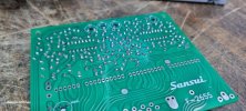
PCB files contributed for redesigned Sansui 9090DB F-2655 Dolby board

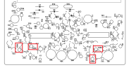
Transistors:

Pulled TR601 (2SC945) from stock board and measured hFE of 258. Went with KSC1815 as replacement, matching hFE of TR01/02 as their collectors are connected.

TR01BCE=64,37.5, 62.5,40, 64,422SC945 (Q,P)KSC1815 179hFE
TR02ECB=56,31.5, 59,32, 61.8,312SC945 (Q,P)KSC1815 179hFE
TR601BCE=5,130, 8.5,130, 12,1302SC945 (Q,P)KSC1815 178hFE
TR602BCE=7,105.2, 10,106, 13,105.22SC945 (Q,P)KSC1815 173hFE
TR603ECB=7,82, 7,85.5, 10,87.32SC945 (Q,P)KSC1815 174hFE

Next intraboard wires, underside resistors, rotary switch and Dolby ICs
 

Attachments

  • 20250202_110914.jpg
    20250202_110914.jpg
    80.7 KB · Views: 30
  • 20250202_110920.jpg
    20250202_110920.jpg
    96.5 KB · Views: 30
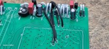
Intraboard links - 20AWG solid. Ensuring not to obscure the rotary switch mount. The switch will need to be mounted AFTER the blue connection from F-2655 (a) to the F-2694 (pots), as its connection to F-2655 resides under the rotary switch.
 

Attachments

  • 20250202_134651.jpg
    20250202_134651.jpg
    92.5 KB · Views: 29
  • 20250202_134656.jpg
    20250202_134656.jpg
    90.9 KB · Views: 29
UPDATE: THESE ARE NOT REQUIRED AS Biroc has shifted them to the top side in this new design - I missed his earlier post

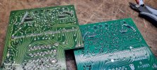
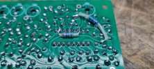
Underside resistors - my original board is Revision A - no underside caps

56KΩ -VE of C19 to pin 5 IC01
56KΩ Junction of C24 and C18 to pin 5 IC02
2.7KΩ pin 2 to pin 6 IC01
2.7KΩ pin 2 to pin 6 IC02

Next external top-side wiring, rotary switch, flat cables then underside wiring
 

Attachments

  • 20250203_072840.jpg
    20250203_072840.jpg
    134.7 KB · Views: 26
  • 20250203_072831.jpg
    20250203_072831.jpg
    96.1 KB · Views: 27
  • 20250203_072826.jpg
    20250203_072826.jpg
    102.5 KB · Views: 26
Last edited:
Underside resistors - my original board is Revision B - no underside caps

56KΩ -VE of C19 to pin 5 IC01
56KΩ Junction of C24 and C18 to pin 5 IC02
2.7KΩ pin 2 to pin 6 IC01
2.7KΩ pin 2 to pin 6 IC02

Next external top-side wiring, rotary switch, flat cables then underside wiring

Those actually go on the top side now, I mentioned it a few posts back but you must have missed it.

1738544657937.png
 
Some prep work needed to F-2654 Switch board

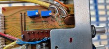
1 cap C07 10uF 16v and 2 trimmers VR02, VR03 100K repalced.
Switches cleaned

Even though this unit had the more robust (too robust!) black ribbon cables connecting F-2654 to F-2655, I wanted to use new flat cables as suggested by Lee (@Overundr1) a while back. These are DigiKey part numbers but I believe Mouser have something similar.

6-way 5" (12.6cm): A9AAT-0605F
10-way 5" (12.6cm): A9AAT-1005F
 

Attachments

  • 20250203_094150.jpg
    20250203_094150.jpg
    101 KB · Views: 34
  • 20250203_094159.jpg
    20250203_094159.jpg
    75.8 KB · Views: 35
  • 20250203_094207.jpg
    20250203_094207.jpg
    74.5 KB · Views: 32
  • 20250203_094215.jpg
    20250203_094215.jpg
    98.6 KB · Views: 37
connection (f) from F-2655 to F2694 is shielded blue. The F-2694 (f) end only connects the core of this cable, however F-2655 connects the core to (f) and the shield to a pad that is untagged on the original board. On the new board, the shield connects to (703) which correctly routes to the (o) intraboard wire. The original board incorrectly labels 703 same as the (i) pad. Well spotted @Biroc
 

Attachments

  • 20250203_101319.jpg
    20250203_101319.jpg
    123.3 KB · Views: 36
  • 20250203_102344b.JPG
    20250203_102344b.JPG
    98.2 KB · Views: 36
  • 20250203_104922.jpg
    20250203_104922.jpg
    66.4 KB · Views: 36
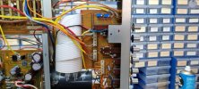
Top side wires and rotary switch installed. Watch those pins on the switch! Only realised I'd bent one when I was down to the last row so had to desolder the lot and carefully re-align the pin - all thumbs today :rolleyes:
 

Attachments

  • 20250203_112237.jpg
    20250203_112237.jpg
    112.5 KB · Views: 40
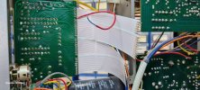
New flat flexi cables installed - pretty fiddly. Could do with an extra inch in length per cable

Seems I have Revision A as I have the red wire from F-2654 to F-2655 which connects to the ribbon cable on the F-2655 via the PCB track.
I have CLOSED the link on the new board
 

Attachments

  • 20250203_141044.jpg
    20250203_141044.jpg
    125.4 KB · Views: 40
  • 20250203_141015.jpg
    20250203_141015.jpg
    91.9 KB · Views: 38
  • 20250203_135444.jpg
    20250203_135444.jpg
    94.3 KB · Views: 38
  • 20250203_135414.jpg
    20250203_135414.jpg
    102.2 KB · Views: 40
Right first time out of the gate!! Amazing work @Biroc -this board is a pleasure to work with! :beerchug:

DBT pass (100W bulb) and full power no smokey :)

All I can test at present is the audio path through the Dolby board as I've yet to restore and install the tuner module.

It sounds brighter to me but still superb. I may change the stacked films on F-2655 back to electrolytic - will use bipolar UDB I have in stock. Also wondering if my rounding up of these caps increased the top end or decreased the bottom end?

C25, 26, 27, 28 increased from 27nF to 33nF due to redundant value

C607 increased from 18nF to 22nF due to redundant value

EDIT: the metal film resistors will also add to the brighter sound and indeed, lower noise floor

I'm rather chuffed
 

Attachments

  • 20250203_143704.jpg
    20250203_143704.jpg
    118.9 KB · Views: 36
  • 20250203_143721.jpg
    20250203_143721.jpg
    70.5 KB · Views: 36
Last edited:
Fantastic news! Very happy to have been able to help. Thank you @BradWil for spearheading the BOM and documenting your assembly in such detail, it's going to make this so much easier for others.

I'm relieved to see everything fall into place and work, I'm sure those that already bought one of these are too! Enlarging the holes for the pots is an easy fix if anyone wants to order a modified version to make it easier to install the upgraded ones.
Very welcome! I'm only getting audio on Aux with the Dolby switch set to off but from memory, this is normal. I'll get to that tuner module soon so we can tick the Dolby function off the list.
 
Without going crazy over the circuit, if you change out the 1uf WIMA for MUSE or other np electrolytic will soften things up a bit. If there is room tack a 0.22uf film underneath. Note those WIMA films seem to take a long time to settle in so may not be worth the effort.
 
Makes sense and similar to what I did on the tone board. Will let it run in for a while - agree they do take time to settle
 
Here is the BOM.

For my build, I used what I had in stock but have created this for those who wish to order the whole build.
I've taken into account lead spacing, physical sizes and specified low ESR caps. You will see a second tab on the my spreadsheet, detailing the order qtys per part number.
  • All items are available at our favourite supplier
  • I have not included the flat cables but you can find them within this thread (different supplier)
  • I encourage you to also run through Biroc's "F-2655_Design _Data" spreadsheet as you build, as it contains a plethora of info
  • Germanium diodes you will need to source if you can find them or simply transfer from the original board
  • NOTE, I have only tested that the audio path from Aux works through this board and have yet to restore and install the tuner module, in order to test and calibrate the Dolby function
  • Plenty of build photos and info back in this thread
Good luck folks, take your time - it would be a headache to troubleshoot if you make an error.

Thanks again @Biroc, you are a legend!
 

Attachments

Last edited:
Without going crazy over the circuit, if you change out the 1uf WIMA for MUSE or other np electrolytic will soften things up a bit. If there is room tack a 0.22uf film underneath. Note those WIMA films seem to take a long time to settle in so may not be worth the effort.
It's already sounding better after only a few hours of running in. I've ordered some Muse UES from our friend, so will wait unil they arrive before I alter the circuit.
 
Back
Top Bottom