

You are using an out of date browser. It may not display this or other websites correctly.
You should upgrade or use an alternative browser.
You should upgrade or use an alternative browser.
Persistent Buzzing When Stylus Makes Contact - Need Help Troubleshooting!
- Thread starter djchaseb
- Start date
-
- Tags
- buzzing uturn uturn orbit
Yes, clever.
By the way:
While you are at it, - I'd suggest you do a pair of shorter RCA-to-RCA runs with something like the Canare L-2T2S.
Cut that cable as short as your rig permits, solder it between the two RCA jacks so that the white wire on both ends is connected to the central RCA pin, and the blue (or whatever the actual color the wires in the Canare cable are) wire is connected to the RCA's outer barrels.
Connect the shielding braid to the RCA's outer barrel on only one side, - this cable end should plug into the preamp's input. This is for one channel.
The other channel is to be connected with another cable of the same design.
The main idea here is to have each channel to use a shielded twisted pair with the shield and the"cold" wire being grounded only at the preamp's input.
Then, with the separate ("black") wire connecting TT's ground to the preamp's shield - you will have the lowest possible hum pick-up.
By the way:
What are your cables between the TT and the preamp?I'm using a simple Technolink TC-750LC preamp which is output to a pair of powered Mackie Monitors.
While you are at it, - I'd suggest you do a pair of shorter RCA-to-RCA runs with something like the Canare L-2T2S.
Cut that cable as short as your rig permits, solder it between the two RCA jacks so that the white wire on both ends is connected to the central RCA pin, and the blue (or whatever the actual color the wires in the Canare cable are) wire is connected to the RCA's outer barrels.
Connect the shielding braid to the RCA's outer barrel on only one side, - this cable end should plug into the preamp's input. This is for one channel.
The other channel is to be connected with another cable of the same design.
The main idea here is to have each channel to use a shielded twisted pair with the shield and the"cold" wire being grounded only at the preamp's input.
Then, with the separate ("black") wire connecting TT's ground to the preamp's shield - you will have the lowest possible hum pick-up.

MuseChaser
Super Member
In cables where the shield is only connected on one end, isn't that end typically the source end (in this case the turntable) rather than the destination (in this case, the preamp)?Yes, clever.
By the way:
What are your cables between the TT and the preamp?
While you are at it, - I'd suggest you do a pair of shorter RCA-to-RCA runs with something like the Canare L-2T2S.
Cut that cable as short as your rig permits, solder it between the two RCA jacks so that the white wire on both ends is connected to the central RCA pin, and the blue (or whatever the actual color the wires in the Canare cable are) wire is connected to the RCA's outer barrels.
Connect the shielding braid to the RCA's outer barrel on only one side, - this cable end should plug into the preamp's input. This is for one channel.
The other channel is to be connected with another cable of the same design.
The main idea here is to have each channel to use a shielded twisted pair with the shield and the"cold" wire being grounded only at the preamp's input.
Then, with the separate ("black") wire connecting TT's ground to the preamp's shield - you will have the lowest possible hum pick-up.

djchaseb
New Member
I’m using monoprice 3 foot. Not sure how good they are, seemed better than the standard run of the mill RCAs. I can possibly move the preamp closer to the turntable and get away with 1 foot or less.Yes, clever.
By the way:
What are your cables between the TT and the preamp?
While you are at it, - I'd suggest you do a pair of shorter RCA-to-RCA runs with something like the Canare L-2T2S.
Cut that cable as short as your rig permits, solder it between the two RCA jacks so that the white wire on both ends is connected to the central RCA pin, and the blue (or whatever the actual color the wires in the Canare cable are) wire is connected to the RCA's outer barrels.
Connect the shielding braid to the RCA's outer barrel on only one side, - this cable end should plug into the preamp's input. This is for one channel.
The other channel is to be connected with another cable of the same design.
The main idea here is to have each channel to use a shielded twisted pair with the shield and the"cold" wire being grounded only at the preamp's input.
Then, with the separate ("black") wire connecting TT's ground to the preamp's shield - you will have the lowest possible hum pick-up.
It is not the source end.In cables where the shield is only connected on one end, isn't that end typically the source end
Don't know what a monoprice is, but three feet is way too much for any cable. You are adding at least 70pF to the input capacitance.monoprice 3 foot
It is better to have the preamp built-in, then you could significantly reduce the input capacitance and increase the input resistance. Doing so you will get the flattest responce all the way up to ~25kHz (where your Ortofon OM5E has the needle+groove resonance) and a bit less preamp's noise.

JP
7480 74111110101115
Don't know what a monoprice is, but three feet is way too much for any cable. You are adding at least 70pF to the input capacitance.
It is better to have the preamp built-in, then you could significantly reduce the input capacitance and increase the input resistance. Doing so you will get the flattest responce all the way up to ~25kHz (where your Ortofon OM5E has the needle+groove resonance) and a bit less preamp's noise.
You're making some very broad assumptions there. There are plenty of low-capacitance cables that can do much better than your claimed 23pF/ft. Loading is cartridge dependent, and last that was said was the cart was an VM95E which is flatter at moderate capacitance.
MuseChaser
Super Member
In cables where the shield is only connected on one end, isn't that end typically the source end (in this case the turntable) rather than the destination (in this case, the preamp)?
Please clarify... I'm not sure what you mean. Are you suggesting that the shield should only be connected at the destination end, or that the turntable is not the source end?It is not the source end.
And, before continuing this cable shield practice discussion further, I am ACUTELY aware of the many different opinions out there about the efficacy of tieing the shield at one end only vs. both ends, the assertions that it helps avoid ground loops (considered a myth in electrical engineering circles, unless the equipment involved is poorly designed in the first place), and the discussions regarding whether to tie the shield at the source end or destination end.
I've built cables both ways. In my systems, there were no advantages to tieing the shield at one end only, so I no longer do so. The best advice, as with most things re/ personal audio, is to try each approach and see what works and sounds best to YOU.
The each cable shield should be connected to the "cold" wire on the cable end that plugs into the preamp's input.Please clarify.
Or, better yet, - the cable shield may have its' own "black" wire that is connected to the preamp's case/box/shield.
In both cases the cable shields are not connected to the TT's ground.
Yes, I forgot that. I saw Ortofon OM5E being mentioned on the U-Turn's site, that's why I referred to it.the cart was an VM95E
There is a nice LCR-calculator somewhere on the net, it shows the resulting frequency response for various cartridges under different C and R loads. If the Cload is made very small (~twenty picoFarads or so) then Rload may be made into hundreds of kiloOhms - which is beneficial in terms of noise.
JP
7480 74111110101115
Yes, I forgot that. I saw Ortofon OM5E being mentioned on the U-Turn's site, that's why I referred to it.
There is a nice LCR-calculator somewhere on the net, it shows the resulting frequency response for various cartridges under different C and R loads. If the Cload is made very small (~twenty picoFarads or so) then Rload may be made into hundreds of kiloOhms - which is beneficial in terms of noise.
Those LCR calculators are rarely of any help as a cartridge doesn't model as simple LCR - in the broadest strokes, the entire mechanical system isn't considered. If we take a real world example, the calculator at alignmentprotractor.com gives the below for an Ortofon Super OM body (580mH, 1k DCR loaded at 105pF and 47k):
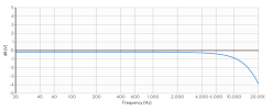
However, here's the actual measured response of that body at various Cl with a Super 40 and Super 30 stylus:


I'd like to see your math on the noise benefit of hundreds of k of Rl, but have to note that 20pF isn't realistic. A typical best-case would be around 45pF to get to the connector on the arm, and then you have to add the cable to the phono stage, the phono stage itself, and strays. The best I can do here is 55pF with about 6" of wire from the arm to the phono stage, and the phono stage is 10pF all-in (measured) at a minimum. Recalculate your electrical response with ~50pF and 100k+ and you may now be introducing issues. Again, very dependent on the cart.
The math about Rinput noise is elaborated in this EW-2003-10 article by Marcel van de Gevel (see attached).
All the difficulties of obtaining low capacitance loads are - alas! - very well known to me. That's why I modding my preamp to implement the 75µs time constant by the cartridge coil's inductance and the input's resistance. Then, as the LTspice model predicts, the input capacitance influence is radically reduced, and even with some ~five hundred picoFarads of input cabling the frequency response remains flat up to ~30kHz. For the abscence of the needle+groove resonance I'm thankful to Stylus 40.
All the difficulties of obtaining low capacitance loads are - alas! - very well known to me. That's why I modding my preamp to implement the 75µs time constant by the cartridge coil's inductance and the input's resistance. Then, as the LTspice model predicts, the input capacitance influence is radically reduced, and even with some ~five hundred picoFarads of input cabling the frequency response remains flat up to ~30kHz. For the abscence of the needle+groove resonance I'm thankful to Stylus 40.
Attachments
JP
7480 74111110101115
Your math in your blanket example. The stylus 40 has a massive resonance around 18kHz - you can see it in the plots above, and more prevalent in the crosstalk shown to you before. It'd be good to see some actual measurements for what you're claiming in regard to that stylus, as it doesn't align with known measurements.

Alas, I did not keep the Stylus 10 response where - along with the usual LRC-peak - the 24kHz high-Q needle+groove peak was clearly seen.It'd be good to see some actual measurements for what you're claiming in regard to that stylus
This high-Q peak is no more with the Stylus 40.
As I'm yet to do the the 75µs at the cartridge, it (the Ortofon OMP) is loaded with the "classic" 47kOhm and sub-optimal 280pF.
For now I'm reluctant to swap the needles to take the Stylus 10 frequency plot again, I have spent quite some time tweaking the cartridge's roll angle to achieve the lowest THD and cross-talk... May be later, when N52 magnets arrive, - I'll tweak the tonearm to implement an electrodynamic damper of its' main resonance (at 13Hz).
I'm talking about the needle+groove resonance only.
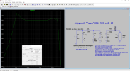
I had to edit the model (Rinp==33kOhm) to make it easier to see. With the Stylus 10 it sits at ~24kHz, I saw it with SpectraPLUS-SC.
With the Stylus 40 I do not see this peak (with SpectraPLUS-SC) under the same conditions in my preamp.
This model does not implement the cantilever's own resonance, so the bulge just above 10kHz is the LCR peak from the inductance and capacitance.
When I properly implement the 75µs time constant by the L×R, this bulge will disappear. Yes, the cantilever's peak will remain, but will it be as prominent on the frequency response? Or will it only affect the channel separation? I do not know yet.
I had to edit the model (Rinp==33kOhm) to make it easier to see. With the Stylus 10 it sits at ~24kHz, I saw it with SpectraPLUS-SC.
With the Stylus 40 I do not see this peak (with SpectraPLUS-SC) under the same conditions in my preamp.
This model does not implement the cantilever's own resonance, so the bulge just above 10kHz is the LCR peak from the inductance and capacitance.
When I properly implement the 75µs time constant by the L×R, this bulge will disappear. Yes, the cantilever's peak will remain, but will it be as prominent on the frequency response? Or will it only affect the channel separation? I do not know yet.
Attachments
Last edited:
JP
7480 74111110101115
I'm talking about the needle+groove resonance only.
View attachment 3443576
I had to edit the model (Rinp==33kOhm) to make it easier to see. With the Stylus 10 it sits at ~24kHz, I saw it with SpectraPLUS-SC.
With the Stylus 40 I do not see this peak (with SpectraPLUS-SC) under the same conditions in my preamp.
This model does not implement the cantilever's own resonance, so the bulge just above 10kHz is the LCR peak from the inductance and capacitance.
When I properly implement the 75µs time constant by the L×R, this bulge will disappear. Yes, the cantilever's peak will remain, but will it be as prominent on the frequency response? Or will it only affect the channel separation? I do not know yet.
Can you share the files that show and don't show this resonance? Where did you pull your model from?
Right now I have only the rip for my Stylus 40. Alas, I did not keep the same rip for my Stylus 10 as I do not intend to return to this needle.
I promise to do such a rip (with the Stylus 10) when I tweak the tonearm more.
The model was borrowed from a Russian-language "Radio" magazine (the year/issue/pages are given as the heading). Its' author re-created the study of famous Japanese engineer/vinyl enthusiast "Josh" regarding the stylus+groove behaviour. (www7a.biglobe.ne.jp/~yosh)
I expected that the FG70 resonance would simply move to higher frequencies, but - most probably because the FG70's contact patch area is so much larger that that of an elliptical needle, that the needle pressure is lower than the vinyl compliance "knee", - the resonance is no more. Looks like the vinyl Q-factor (the R1) and compliance (the C1) under the FG70 needle dampen it very well. And FG70 is significantly lighter than the bonded 10.
I wish I had the whole line of stylii: Stylus 5S - as the reference, Stylus 20 and Stylus 30, to check how the ETM and needle shape affect the model's R1 and C1.
Here is the Stylus 40 rip (192/24, TF==2grams, after my best attempt of zeroing-out the roll angle). The RIAA preamp is "classic", so the LCR parameters are sub-optimal still. The tonearm+cartridge resonance is yet to be damped, right now I'm working on that. The test record used is this.
I promise to do such a rip (with the Stylus 10) when I tweak the tonearm more.
The model was borrowed from a Russian-language "Radio" magazine (the year/issue/pages are given as the heading). Its' author re-created the study of famous Japanese engineer/vinyl enthusiast "Josh" regarding the stylus+groove behaviour. (www7a.biglobe.ne.jp/~yosh)
I expected that the FG70 resonance would simply move to higher frequencies, but - most probably because the FG70's contact patch area is so much larger that that of an elliptical needle, that the needle pressure is lower than the vinyl compliance "knee", - the resonance is no more. Looks like the vinyl Q-factor (the R1) and compliance (the C1) under the FG70 needle dampen it very well. And FG70 is significantly lighter than the bonded 10.
I wish I had the whole line of stylii: Stylus 5S - as the reference, Stylus 20 and Stylus 30, to check how the ETM and needle shape affect the model's R1 and C1.
Here is the Stylus 40 rip (192/24, TF==2grams, after my best attempt of zeroing-out the roll angle). The RIAA preamp is "classic", so the LCR parameters are sub-optimal still. The tonearm+cartridge resonance is yet to be damped, right now I'm working on that. The test record used is this.