• The move to the new server is done. There are some software and database maintenance updates in process. This has us passing the hat around to help out. We appreciate any donations. Seriously, even a dollar helps. The payment page may be found here - https://www.audiokarma.org/support.html

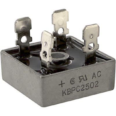
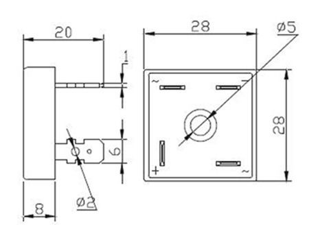
Phase LInear 300 sii bridge rectifier

bigdano123

New Member
I replaced the bridge rectifier in my PL300 sii. I normally take a picture before doing something like this, but this time, I relied on my 72 year old brain to remember what goes where (BIG mistake). Could someone who has a working 300 post a pic of the bridge rectifier in circuit so I can double check what I did? Thanks.
 
Register to hide this ad
What did you do? Short something or it just doesn't work?

Bridge rectifiers are easy. There are only two AC inputs and two DC outputs. Of course the DC output is marked (should be) negative & positive.
 
That's my problem. I ordered the correct replacement. The only marking on the replacement was for one pole of the AC. I know that the diagonal pole is for the other
AC input. My concern is the other 2 poles for the DC out. I just want to make sure that I've got the right wires going to the right place on the DC side. The amp is a work in progress so I don't want to ruin anything by having the wiring incorrect.
 
plus should be the blade that faces the other way
pic of one here .....

70015997.jpg
 
That is the way I have it wired. I am getting 155.2 v across the DC connections. Relative to ground I am showing from the pos side 100.5 V. Neg side relative to ground I am getting -65.8 V. Does that sound correct?
 
I see from the schematic for the 300 that I should be seeing +70 and -70 volts going to the channels. That is why the 100.5 V showing on the positive side concerns me. Is it possible that I have a defective filter cap?
 
OK. Here is what I've got. The left and right channels are connected to the PS. I identified bad outputs on the right channel board, so I removed them. So the left channel is fully loaded, the right channel is connected but has no output transistors on the board. I will disconnect the boards from the PS later today and retest the voltages at the rectifier and then get back to you. Just want to thank you for your help so far.
 
From what you have said prior, I am pretty convinced that I didn't screw up the connections, so I don't think a pic is really necessary. Thanks, though
 
I disconnected both of the channel amps from the PS. DC voltages at the output of the Bridge Rectifier pretty much remain the same as before
 
I soldered as they were originally. Here is a little more info. I powered on the amp and allowed the filter caps to charge. I powered off the amp and (carefully) removed the buss bar between the 2 filter caps. I measured the DC voltage across each of the caps. One cap was showing over 62 volts DC, the other was showing virtually no charge. Does that point to a bad cap or a bad bridge. Don't really know. I'm not a tech and know only enough to get myself in trouble.
 
Last edited:
That's my first insinct, BBUUTT, a bridge is about $6, a pair of new filter caps around $100. I probably will get another new bridge and check for the same readings. If a new bridge doesn't fix it, I know I'm going to have to dip into savings. Thanks again for sticking with me on this. Folks at AudioKarma are great!!
 
. I powered off the amp and (carefully) removed the buss bar between the 2 filter caps.
When you removed the bus bar, you are floating the ground, and all voltages will be strange. Need to have bus bar installed and connected to transformer for voltages to be correctly measured.
 
Back
Top Bottom