• The move to the new server is done. There are some software and database maintenance updates in process. This has us passing the hat around to help out. We appreciate any donations. Seriously, even a dollar helps. The payment page may be found here - https://www.audiokarma.org/support.html

Phase Linear 400 - DC offset problem

audiogymp

Active Member
I've recently replaced the output transistors on one channel of a PL400 I'm working on but I now have a big DC offset.

When I got the PL400, it arrived with no main fuse. On DBT (with fuse) it drew too much current. Measurements indicated that three of the connected outputs on one channel were conducting C-E (one measured alright out of circuit). With the three removed, the current draw looked normal on DBT.

I got some helpful advice from AK people and replaced the outputs on the bad channel with 6 MJ21196G. After I put them in, the amp looked alright on DBT - surge while the caps charged and then low draw. But now the DC offset on the channel I replaced the outputs on is almost 40V (not sure what it was before).

An obvious answer might be that the Dc offsetmeans that there is a problem with driver or output transistor. But I'm not sure that this makes sense because the current draw on DBT (no speaker load) settles to a low draw and I would have thought that the current would stay high if there was a driver or output problem.

The Amp is a series 1 with the PL14A board. I measured the bias [Edit:"DC offset" corrected to "bias"] on the good channel - about 0.29V for both R38 (recommended for measuring bias ["offset" corrected to "bias"]) and also on the corresponding R39 for that channel - ie within spec. On the problem channel, R38 is normal (about 3.1V) but R39 measures zero (ie 0.000V). The resistance measure across R39 is about 17 Ohm in circuit (it is a 10 Ohm resistor).

I'm not sure what to check next and would appreciate a nudge in the right direction.

Thanks, Jon
 
Last edited:
Register to hide this ad
I had a number of off value resistors on the driver board for my PL 700. Maybe worth checking that out and replacing them as needed. Won't guarantee that will sort it, but it probably won't hurt any. If you're getting 17 ohms in circuit on a 10 ohm resistor, its off value considerably. If anything it should read below marked value.
 
I see that I made an error in my original posting - in the second last paragraph I referred to DC offset when I meant to refer to bias/idle current. I hope this didn't put anyone off.

Gadget, I see your point. If R39 has gone high, it could be causing excess DC to be delivered to the base of three outputs, which could deliver amplified DC to the speaker output. It still seems surprising that the voltage across R39 is 0.000V but its hard to explain this in any event.

I'll replace R39 and post the result. I assume 1W carbon film type resistors will suffice. Please let me know if I need something higher spec.

Thanks.
 
ok, totally different problem.

If you've got 40 volts across the emitter resistors and flames aren't coming out if it, my vote is on the emitter resistors being bad. If the outputs shorted, this is pretty much to be expected. Not sure what the 400 uses, but my 700 I think runs 0.33 ohm. If you're measuring anything over 1 ohm, they're bad. Most meters will not accurately read low value resistors unless you've got a 4 lead setup.
 
I replaced R38 and R39 on the problem channel with new resistors. Interestingly, the corresponding resistors on the good channel look like they might have been replaced at some stage. When tested out of circuit, the old resistors measured at around 15-16 ohms (contact on alligator clips might have elevated the reading in circuit).

The change of resistors made little difference to the DC offset - still almost 40 volts. However, when I made the bias measurements again, there was a change. R38 sat at about 0-3 mV. R39 was no longer at .31V but had dropped to 0.18V, about half the correct bias voltage.

I tried making the bias adjustments. On the good channel, it settled in nicely at 0.35V. On the bad channel the bias adjustment made no difference - R38 stayed close to zero while R39 was constant on 0.18V.

I visually checked the 2N3403 transistor (which has been referred to as the bias transistor) for the bad channel to make sure that the terminals were in tact because they are known to break off - they were in tact.
 
Hi Gadjet

I didn't see your reply until after my last post. I'll try the emitter resistors next. I can't measure below an ohm but I expect that they'll have a higher resistance if they're toast.

Thanks, Jon
 
I think I'm getting confused. Where are you measuring 40 volts, across the emitter resistor or at the speaker terminals? Speaker terminals is offset, across the resistor is bias.

If you've got 40 volts of offset, its probably one of the upstream transistors on the driver board, or something connected to it gone bad. I had several off value resistors on my PL 700's board. On my friend's 700, one of the transistors in the protection circuit was bad and was causing it to make triangle waves.
 
The almost 40V offset was measured at the speaker terminals. Re-measured just now at 37V.

I hadn't recently checked the rail voltages. I'm pretty sure they were correct when I identified the bad transistors, which have now been replaced. However, I measured the rail voltages just now and they are out - only +/- 42V.

Rail voltage is obviously a problem but it it is curious that only one channel has DC offset and bias issues.
 
I have 2 PL400's in the shed waiting for some attention so I'd thought I'd practice...
First up, I wouldn't call this a dc off-set issue which 1 would limit to 1 volt.

Possibly you have a transistor that is failing/leaking(?) under load. Diode testing
will show all is ok, but it breaks down under voltage. Candidates are Q8,10,11,13,15,17.

Measure dc voltages, black probe connected to black speaker post
1) red probe at red speaker post, previously measured 37V, need confirm this is +37V
2) red probe at Q17e/R45 junction
3) red probe at Q15e/R43 junction
4) red probe at Q13e/R40 junction
5) red probe at Q11e/R38 junction

For tests 2)-5) the voltages may be quite small, maybe mV. Very important to note the sign
+/- of the voltage. A + sign indicates probable problems with that transistor.

If no joy continue with,

6) red probe at Q11b/R36 junction (if test 5 positive)
7) red probe at R27, R32 junction (if test 4 positive)


Has C11 and C15 been replaced, caps can leak volts...
 
Correction to above procedure.

Measure dc voltages, black probe connected to black speaker post
1) red probe at red speaker post, previously measured 37V, need confirm this is +37V

Move black MM probe to red speaker out/post. For tests 2)->7)
2) red probe at Q17e/R45 junction
3) red probe at Q15e/R43 junction
4) red probe at Q13e/R40 junction
5) red probe at Q11e/R38 junction

For tests 2)-5) the voltages may be quite small, maybe mV. Very important to note the sign
+/- of the voltage. A + sign indicates probable problems with that transistor.

If no joy continue with,

6) red probe at Q11b/R36 junction (if test 5 positive)
7) red probe at R27, R32 junction (if test 4 positive)


Has C11 and C15 been replaced, caps can leak volts...


Apologies for stuff up.
 
If the rail is at +/- 42v and the speakers are seeing 37, thats pretty close to shorted transistor performance. I want to say the rails on those are supposed to be 70 or 75 volts.

Curious if the low supply voltage is caused by high load, or if there is something else going on. Does the voltage on the power supply go normal if you remove the rail fuses from their holders? (the 700 at least has 4 holders over by the speaker terminals for this purpose) That would isolate the amp from the supply and rule out any sort of load issues.

If its still low, verify AC voltage into the bridge rectifier. If it should be 70v out, it should be around 100vac across it, or 50vac from ground to each AC lead.
 
When all else fails, go to the experts on the Phoenix Audio Forum and your problem will be solved very quickly. Phase Linear is all they do as well as the White Oak monsters
 
Hi mbz

Thanks, and nice to be getting some help from close to home. I did measurements 1-5 from bad (+38V offset) and good (-6mV offset) channels. The results look significant, so I didn't continue with 6 and 7.

(1) confirmed: black probe to black terminal, red probe to white terminal (which is red on other channel), +38V
(2) bad channel, +38V; good channel, -2mV
(3) bad channel, +38V; good channel, -5mV
(4) bad channel, +38V; good channel, -5mV
(5) bad channel, +38V; good channel, +330 to +350mV

Apart from Q11, the other transistors measured (in fact all outputs on this channel) are brand new, so I hope none of them are now toast. Before I replaced them, two out of Q14, Q16 and Q18 were conductive E-C and the DBT stayed bright when the unit was powered. It's not behaving like this with the new Xistors.

Another observation: I previously noted that R38 and R39 had been replaced on the good channel. It also looks like R36 and R37 have been replaced on the good one. They are still original on the bad channel, although I have replaced R38 and R39.

I don't know if this is significant but (as is apparent) the DC offset is half the rail voltage. The bias (which I couldn't adjust on the bad channel) was zero at the recommended measurement across R38 and half the correct value across R39 (as expected, the values are the same across these resistors on the good channel).

Gadget - the emitter resistors on the bad channel were all reading about 1 Ohm, which is about as low as my DMM will go. As for the power supply, I have 71V AC going in (about 35V each side relative to ground) and 84V DC coming out. I then get 42V across each of the big supply cans.

I have a 30W bulb in my DBT. I know this is low but it's not running bright once it settles, so I assumed it's not restricting supply much. Is this an issue?

Cheers, Jon

ADDENDUM

Rail voltages appear to be caused by DBT.

Readings above were done with mbz's earlier post and the corrected measurements were done. mbz's corrected measurements were redone with 70W bulb.

Rail voltages with 30W bulb recovered somewhat with fuses removed. With 70W bulb and fuses removed, rails were at +/- 70V. With fuses replaced and 70W bulb, they were at +/- 64V.

mbz's corrected measurements done with 64V rail voltages resulted in all +38V readings above being -58V instead.
 
Last edited:
mbz's corrected measurements done with 64V rail voltages resulted in all +38V readings above being -58V instead.
The good news is that the voltages are negative, means the speaker line is at a higher voltage than the emitters of Q11,13,15,17.
Suggests these TR's are OK. I'm concerned that the voltage is -58, that's a lot of volts. Apologies but I think/hope you've made a mistake, 58V across a 0.22ohm emitter resister is 260Amps! (15kW).. Black probe connected to red speaker post of problematic channel?

The remaining candidates are Q8(c-e short?) and maybe Q1,2.
With black probe in red speaker post measure dc voltage with red probe at,
- Q8 collector/D9 junction
- R15(10k) at R15/R10/R13 junction, expect this to be negative.

Going back to tests 2)->5) I'm trying to work out which voltage is higher, the speaker line or the transistor emitter. If the emitter is
higher then transistor suspect faulty. I would expect a few mV in each case.
 
I see your point. After addressing rail voltage I must have left the black probe on the black terminal and made measurements relative to ground.

I redid the measurements and this time the results were as follows:
(2) 0mV
(3) 0mV
(4) -5mV
(5) +290mV
... so much more like the measurements from the good channel, and no need to worry about a blackout in the area.

The further results are:
Q8/D9: +1.28V
R15/R10: -19.6V

FYI - I think the values of R10 and R15 have been reversed on the schematic.

Also it is now apparent that R11 and R15, together with a few of the caps have been replaced on the side of the board for the good channel.
 
5) red probe at Q11e/R38 junction
Gave +290mV above the speaker line, that's above the 40 or so volts on the speaker line.
This indicates a problem. Candidates are Q11(c-e or b-e breakdown), Q10(c-e breakdown) or
C11 leaking volts.

Q8/D9: +1.28V This is inconclusive, maybe ok.
R15/R10 = -19.6 indicates source of higher voltage to the "right" of R10/R15, ie, Q8 etc...

Suggest replace C11(47uf/50V), it's probably OK but it's easy, removes one possibility.

Measure Q11base/R36(150)/Q10emitter junction using red probe, black probe connected to
red speaker post. If this voltage is positive (maybe +1.5Vdc or higher???) then Q10 is
suspect/replace. If the voltage is negative (-40V or so??) then replace Q11.
 
OK. I see your point on Q11. The bad channel seemed to be consistent with the good channel, so I'll check both again.

Are we using Diagram III-5 in the SM as a guide for expected voltages? It says it's for "PL14" without specifying A or B but looks pretty close to the PL14A circuit. That said, R10, for example, is 27K on this diagram whereas it is 10K on the diagram for PL14A (and 12K on the amp's PCB). I expect the diagram would still be indicative. But if so, would it make sense to make measurements relative to ground? I'm not questioning the logic, just trying to understand.

I have a few 47uf left over from another project, so I will check/replace in the course of measurements.

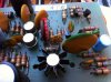
I have attached a photo of C7, which has spots which might be the sign of some sort of corrosion/degradation. The corresponding cap on the other channel looks much the same - I was going to replace these in due course but they now look a little more relevant. All of the other ceramic caps on the board look OK. In light of your proposed measurements/comments, this could be a possible source of positive voltage. I'll get some 120pf replacements and have ready to swap over.

Thanks, Jon
 

Attachments

  • IMG_0382.JPG
    IMG_0382.JPG
    90 KB · Views: 58
Hi mbz

Perhaps I have something quite wrong. However, shouldn't we expect to see + few hundred mV when measuring from the Q11e/R38 junction to the speaker terminal (negative/black probe to the red, cf white, terminal)? The bias setting is made by setting the voltage across R38 to 350mV (negative probe to the speaker terminal side of the resistor - see SM section V, Step #6, (b)). As I said, I may be completely wrong but I can't help thinking that's what we're seeing here.

Using same speaker post connection (black probe to red, ie white), the measurement from Q11base/R36 came in at +912mV. Diagram III-5 says +1V. Should we treat this as not indicating a problem?

I replaced C7 and C11 on the problem channel. Old components were a little off stated value but within rating. This made no difference to DC offset etc. This is not a nice board to work on. I can see why some are prepared to junk it and slot in a replacement board.

FYI - with the 70 bulb in DBT and 64V rail voltages, the DC offset is now 58-60V, not 40, as it was with 30W bulb.

Cheers, Jon
 
OK. I see your point on Q11. The bad channel seemed to be consistent with the good channel, so I'll check both again.
The main difference between good and bad channel is it extra 58-60V on the speaker line. Need to track down the source of this
voltage by moving in the direction of increasing voltage with respect to the red speaker post. That will appear as positive voltages
on your MM. So far we are at Q11emitter, maybe this is due to a c-e near short? Or maybe the path is via R36 or C11???

Are we using Diagram III-5 in the SM as a guide for expected voltages?
Thanks for the tip, I was working from the 14A schematic only. Yes these voltages would be close enough.

But if so, would it make sense to make measurements relative to ground? I'm not questioning the logic, just trying to understand.
In some cases the increase in voltage may be only a few mV, like a voltage drop across a resistor, this would not be discernable on a 100V
scale. Measurements with respect to ground is perfectly ok however we are less likely to make mistakes this way.

I have attached a photo of C7, which has spots which might be the sign of some sort of corrosion/degradation.
I don't see how C7 would cause these high voltages, more likely a failing transistor

Perhaps I have something quite wrong. However, shouldn't we expect to see + few hundred mV when measuring from the Q11e/R38 junction to the speaker terminal (negative/black probe to the red, cf white, terminal)
The voltages at III-5 have Q11e at about +300-350mV and yes we are seeing that and yes this could be a wild goose chase.
What we don't expect is about 55-60V at Q11e. Where is this voltage coming from.

Using same speaker post connection (black probe to red, ie white), the measurement from Q11base/R36 came in at +912mV. Diagram III-5 says +1V. Should we treat this as not indicating a problem?
This kinda suggests an earthing issue where everything is shifted by xx volts. Subtract this offset (58-60V) and everything falls in place.
Measure the positive and negative rails with respect to ground, expect +/-75V or there abouts. If it was an earth issue you would have
+150V(pos rail) and 0V(neg rail) or there abouts, so I don't think this is an earth issue.

Measure Q11base/R36(150)/Q10emitter junction using red probe, black probe connected to
red speaker post. If this voltage is positive (maybe +1.5Vdc or higher???) then Q10 is
suspect/replace. If the voltage is negative (-40V or so??) then replace Q11.
For me, this is the next step.
 
Back
Top Bottom