• The move to the new server is done. There are some software and database maintenance updates in process. This has us passing the hat around to help out. We appreciate any donations. Seriously, even a dollar helps. The payment page may be found here - https://www.audiokarma.org/support.html

Phase Linear 400 - DC offset problem

I hope that the 20Hz is well below the operating limits of your signal generator/sound card(?), the previous test at Q1b should confirm this.
Otherwise the next step would be to find out where the distortion is introduced and replace the offending part. I'm very reluctant to suggest/go
down this path since both channels are equally affected. Maybe wait overnight for AKers in the US to chime in.
 
The third pic in #114 is perfect, nice symmetric clipping. With lower frequencies, especially around line frequencies, 50/60Hz, and power supply ripple frequencies, 100/120Hz you might see strange things if you can monitor the distortion. Using my Sound Technology distortion analyzer I will usually hit 20, 200, 2K and 20K and all will look OK but the distortion signal at 200 will look different than the rest due to the 120 ripple of the PS. Anyway you should be safe to load the amp and run at 1KHz or 2KHz to see what you get. Worry about the freq. extremes later if there's a problem.

Craig
 
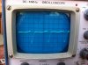
It turns out that the clipping I observed was coming from the signal source. I attached a buffer to the computer output to boost the signal, which produced output from the amp that was beyond the largest scale on the scope.

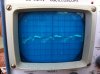
My scope now seems to have stopped working - there's a messy looking background oscillation and it's become quite insensitive to input signal. The manual says it should take up to 280V RMS input and I can't have exceeded that. But it is fairly old. The scope failed before I could get a better idea about clipping/distortion.

I'll see if I can find another scope but it may take time.

PS - this is available locally, although it'll be a trip to collect it:
http://www.ebay.com.au/itm/Hitachi-...494214?hash=item1c8e6b8086:g:fsgAAOSwLgtZkXVc
There are a bunch of digital/LCD things on offer. Are they better options?
 
Last edited:
The digitals are sexy and small, and they have nice things like storage and many will do FFT (basically spectrum analysis) but that comes at a cash cost. For my own purposes, the old B&K that I got nearly for free and have had for years does the trick.

Not sure what things are like in your area, but around here you can often pick up a CRT scope at a hamfest for very little. Maybe worth a look for such an event.
 
False alarm on the scope.

I rechecked function of scope with different leads and it seems that the probe I had been using was causing the problem. The probe had high RC impedance and perhaps the internal circuity/lines developed an issue. I swapped for leads without impedance and the scope seemed to work fine again.

Again using the computer with buffer to increase signal.
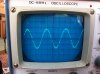
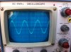
  • 200Hz - symmetrical clipping on both channels (bit of chatter from the meters on the amp)
  • 2KHz - symmetrical clipping on both channels
  • 20KHz - symmetrical clipping on both channels; a bit of harmonics/oscillation on the trace that gets more prominent towards and at clipping
  • 20Hz - I could just push the right channel (not the one being worked on) to clipping with a bit of slope on the clipped part of the waveform. The left channel only reached about 80% of the amplitude of the right and would not clip.
Does this suggest issues at the pre-driver stage or should I proceed to test under load?
 
Upon testing the left channel did you run out of input signal from your source? If so the left has lower gain than the right channel. Do both channels have the same parts? R10, R13, R15 and C6 are the feedback components and set the gain.
 
I had several off value resistors on my driver board. Don't know which but its worth checking. A whole bunch were way off on my friend's Series II 700.
 
R10 and R15 have been replaced with newer looking components on the right channel (the one that clipped) the other components IIwhtt mentioned are original. I replaced C7 on the left channel (the original on both sides look corroded). The replacement is 50V instead of 100V but I now have a correct replacement. This might be doing something to the feedback. Notably all the electolytics on the right channel save for C3 and C6 have been replaced at some time in the past too.

I plan to replace the remaining old electrolytic caps once I have the amp going (C6s included). This might be a good time to check resistors.

The distortion I noticed when I tried to listen to the amp seemed to be at 1-2 orders of magnitude below clipping, where the signal traces in this run of testing all look nice and clean. Is that a separate problem? If it is, should I deal with that first?
 
Been lurking in te background while others run with it. What's the latest status, still low gain on left channel? and distortion prior to clipping?
 
Things looking positive. Amp appears to be working now (subject to what I observed on the scope) but I'll post details of the last stage of testing for those that might be interested.

I followed step #4 of the test and alignment procedures with step #5, using my 16 Ohm guitar attenuator as a dummy load. I got symmetrical clipping at 20, 200, 2K and 20K Hz, with output voltages of 60-70V from baseline (ie 120-140 peak to peak). My DMM measured about 40 and 45V respectively, so it looks like I got about the 40V RMS the SM specifies. Left and right were fairly symmetrical in output, so the lower gain on the left channel was not apparent under load.

Am I right in thinking that I would have got higher outputs before clipping if I had the 8 Ohm load specified?

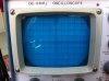
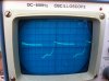
I then looked for the crosstalk/distortion I had observed on the right channel. I did testes where the signal/load were on one channel and the scope took the signal from the other. There was generally a little crosstalk going from right to left, particularly near clipping. There was more going the other way (consistent with what I'd previously heard) and the following traces are attached.
  1. measured from right channel with left well below clipping at 20Hz (~1V/div)
  2. measured from right channel with left well below clipping at 200Hz (~1V/div)
  3. measured from right channel with left well below clipping at 2K Hz (~1V/div)
  4. right channel at 20K Hz at about half clipping output (signal/load/measurement on same channel) (~20V/div)
  5. left channel at 20K Hz at about half clipping output (signal/load/measurement on same channel) (~20V/div)
  6. measured from right channel with left well below clipping at 20K Hz (~1V/div)
  7. measured from right channel with left at about clipping at 20K Hz (~1V/div)
After measuring these traces, I thought I had visualised what I'd previously heard. But since I'd been able to take the amp to clipping without problem, I gave speakers another go. This time somewhat better speakers and I used the buffer between the iPod and the amp.

This time it sounded pretty good and I couldn't hear any of the things in the traces (I did the same test for crosstalk by listening instead of taking a trace and it was quiet). Not sure why it was different. I've used the same speakers and iPod as a source before - not the best way to hear an amp but it's usually pretty obvious once the amp is fixed.

Any comments before I start the lap of honour (caps, cosmetics, etc)?

 

Attachments

  • IMG_0400.JPG
    IMG_0400.JPG
    65.7 KB · Views: 13
  • IMG_0402.JPG
    IMG_0402.JPG
    60 KB · Views: 13
  • IMG_0404.JPG
    IMG_0404.JPG
    67.3 KB · Views: 14
  • IMG_0406.JPG
    IMG_0406.JPG
    76.6 KB · Views: 14
  • IMG_0407.JPG
    IMG_0407.JPG
    81.8 KB · Views: 15
  • IMG_0409.JPG
    IMG_0409.JPG
    76.3 KB · Views: 14
  • IMG_0410.JPG
    IMG_0410.JPG
    71.9 KB · Views: 12
  • Like
Reactions: mbz
Congradulations, there were some (NW) that were sure you wouldn't get it up and going without WO help/upgrade.
It's late, will take me some time to go over the cro traces. Might be an intermittent problem. I'd be very tempted to
replace the main filter caps, they are very undersized and old...
 
If the crosstalk was measured with no load on that side, it may be part of it. Likely what you're seeing is the power supply swinging and inducing signal on the silent channel. Could be the power supply caps aren't in perfect shape, but honestly thats just something that can happen with single supply amplifiers. I have never made that measurement on my 700 so I can't say whether it does the same thing.
 
  • Like
Reactions: mbz
The amp is up and going, ie, not a basket case. I would roll the dice a little and only replace the main caps and then check performance
crosstalk etc... Currently on local bay are a PL700II, not working AUD355-, PL400 working AUD695-
 
Thanks to everyone who has been following this thread and particularly mbz for all the generous help (in saying that, I hope I'm not speaking too soon).

mbz - are you suggesting not replacing the old electrolytics on the driver board at this stage? Is that because you think the supply caps should be done first or because you think the caps on the driver board are not very important. There was an earlier comment that replacing the caps on the board didn't make much difference. But a lot of people are suspicious about old electrolytics and are quick to replace.

As for the supply caps, the current ones are 5,900MFD/85V. Are you able to suggest ball park figures for the values I should be looking for? I might also replace the rectifier at the same time - will look for something around 8Ohm, because tha't what the main fuse will allow.
 
I was under the impression you were unsure which path to take, recap etc or WO upgrade. Certainly I would replace all electrolytic caps
and other problematic components (trimmers, out of spec resistors, and,,,). By replacing the main caps only it keeps your options open
regarding the WO upgrade and allows you to make further assessment on amps stability. The main cap upgrade should improve stability
and sound quality. Alternatively, if you want to go for the full recap, there are only a few... and saves on repeat mouser orders.

Regarding main caps, ballpark 15000uf/100V, hopefully gadget73 will chime in with first hand knowledge. Biggest problem will be the
available space. I've used United Chemicon seem ok, I would go 85C rather than 105C since the ripple and tan delta/esr ratings would be better
(with 85C). Find 3-4 with the wanted dimensions then select lower tan delta/esr.

Regarding the rectifier, I'd be inclinded to bump this up also, 10Amps at least, pay a bit extra for fast/ultra fast or soft recovery or no recovery or...
price difference is minor, make sure they are heat sinked.
 
I don't know the 400 specifically to be honest. I just know its very similar overall to the 700, but less transistors and lower voltage rails. Same driver boards used on both models though.

When I replaced the caps in my 700, the new ones are 16,000 uf @ 160v vs the original 9800uf @ 100v. My rails ran at 103 volts, so the stock rating just wasn't enough for me to be comfortable with. I did upgrade the rectifier at the same time. I think its a 25 amp unit that i went with, nothing overly exotic, just something new and common from Mouser that fit the original footprint. In the 700, the rectifier bolts to a large hunk of aluminum that is used as the "saddle" for the big capacitors to sit in.

Not sure what the 400 uses, but if the caps are barely rated for the voltage I'd give them a bump. I do believe the physical sizing is a more common one than the 700, so you can probably lay your hands on something without any special effort. The guys over at Phoenix can likely steer you in the right direction there.
 
  • Like
Reactions: mbz
Congradulations, there were some (NW) that were sure you wouldn't get it up and going without WO help/upgrade.
It's late, will take me some time to go over the cro traces. Might be an intermittent problem. I'd be very tempted to
replace the main filter caps, they are very undersized and old...

I never said it could not be done but I am willing to bet something else will go south though I pray it does not and get to enjoy it for awhile. I recommended the WO options because the amp is 100 times better sounding and reliable. The traces on the control board are a nightmare, the board is brittle from age and the TO3 stuff in the back can be very problematic. Congrats getting it going but keep the WO version in mind for someday when you have the extra coin. You will be blown away, like night and day
 
Once again, thanks all.
I'll deffo upgrade the supply stage and I'll be using a speaker protection circuit while the amp's in original format.
I've learnt a lot from your patient guidance, including why most people just junk the driver board.
I expect I'll fit some WO when the project loop brings me back to this one.

I'll post if anything interesting comes up.

Cheers, Jon
 
Back
Top Bottom