• The move to the new server is done. There are some software and database maintenance updates in process. This has us passing the hat around to help out. We appreciate any donations. Seriously, even a dollar helps. The payment page may be found here - https://www.audiokarma.org/support.html

Phase Linear 400 - DC offset problem

I take your point on Q5b-e. The measurements I took were to get a big picture idea of whether things were more like what we see in III-5. I can measure Q5b-e directly but Q5c has gone from near +ve rail to -0.8V, which is a pretty good sign that things around Q5 are behaving better. It also suggests that things around the bias control circuit should be returning to normal - will check.

I had a look through the Pheonix post and it was interesting but it appears that the latching-up involves Q2c going high (to 29V). It was a little hight before Q5 and Q4 replacements (23.5V) but is now about 11V (cf III-5 value of 21V). It looks a bit like the latching situation creates a similar scenario to what we would expect if Q4 failed OC, as we suspected.

If I take the precaution of doing the Phoenix fix, could I confirm that it involves putting two diodes in parallel (opposite direction) across the terminals of C6? Do I have this right?

I will do some more checks. I should be able to take PL400 off the DBT at some point because it doesn't appear to want to run away. I have to confess that, with my limited knowledge, disabling something called an over current protection circuit involves a bit of trepidation. It makes sense as a diagnostic step but it didn't make any difference and the idea of limiting over-current seems not unimportant. Is there some learning that the circuit is ineffective or prone to cause problems?

Thanks, Jon
 
Regarding Q5, agree things look better.
Regarding the pheonix fix on Q6, yes 2 diodes in parallel, opposite directions connected across C6 terminals.
This is not mandatory but preferred/added protection.
Understandable reaction to passivating over current protection circuit. OK to reconnect diodes.
Maybe do in steps by changing wattage of DBT?
 
Qualified success - amp plays music but issues at higher volume.

On DBT I measured:
Q5b-e: 0.63 drifting to 0.59V - perhaps enough to open Q5
Q10b: 1.4V (cf 1.6 in III-5) - suggests appropriate current level through path of R17 to R20
I was able to set bias (not possible before). 2mV offset on both channels.

I then reconnected D9,10 and re-checked bias - not much difference but slight re-adjustment. Offset same.

I then connected test speakers and input signal while on DBT (70W). I used the speaker protection circuit - mostly to protect silicon in event of excess current. Worked fine at low/moderate level but signs of instability in globe and distortion if volume increased. With 116W globe (highest wattage I could find), volume got a bit higher before same effect. Suspected supply limit might be causing problems when current draw increased, so removed DBT.

Amp worked fine up to moderate/louder moderate level. Going louder it starts to produce distortion (VU meters twitching to the 20 mark, less than 10% of meter range). With signal only to the right channel (not the one being worked on) it seemed to sound OK but I wasn't keen to push it. With signal only to the left channel, distortion increased with volume over moderate level and there was also an increasing low volume but heavily distorted sound coming through the right speaker (which had no input). Again, didn't want to push it.

Speaker protection didn't engage (might have been a transient trip/re-engage at one point).

I'm thinking that the distortion on left channel might be connected to distorted signal leakage to right channel. Any thoughts/experience with something like this?
 
Q5b-e 0.59-0.63V is ok.
If Q5 was not turning on you would be back to square 1 with 60Vdc+ on speaker rails.
Q10b, agree looks ok
Able to set bias, very good news.

Regarding the distortion, some general comments.
While most transistors have been replaced you still have old diodes and caps.
The main filters are very small for the task and they are old...
The troubleshooting section gives some hints on oscillation etc... worth checking.
Also the service bullitens talk about oscillations and soldering a 10-33pf/100V
cap across the b-c of a predriver transistor.

An oscilloscope is really needed to see what's going on.

I don't see anything in the schematic that would explain the crosstalk.
Maybe something physical, rca connections/grounding. Again a cro would make
life easier.
 
See what the output waveform looks like. When I fixed my friend's PL-700, it was outputting triangle waves above a watt or so of output power. It was a problem in the protection circuit, I forget specifics but it ended up being a bad or wrong transistor that someone had installed.

If the filter caps were completely shot you might be modulating the power supply rail enough with one channel to make some noise in the other. Beyond that, agreed on grounding or wiring issues.
 
  • Like
Reactions: mbz
I have a scope - a vintage, single channel unit. I don't have a signal generator or any source of input other than music. That said, I have a tuner that puts out something that sounds like a sine wave at mid-audible frequency for setting recording level (I think for recording radio to tape). Might be better than nothing. Is 50Hz useful? and is there some simple circuit to tap it off mains?

If it was a power supply issue, would I expect symmetry between channels?

BTW, when I took the unit off the DBT, rail voltages were +/- 75.5V, not the 80V shown in the schematic.
 
I've used computers with software to generate sine waves. Audacity is free, and it'll make whatever your sound card can spit out. If you don't have a computer at the bench, make an audio file of a tone, burn it to CD or dump it on an ipod type thing and run that. The frequency isn't terribly critical, it just needs to be something in the audio range and be of the right shape. You're mostly looking to see if the shape going in is the shape coming out. You also want to be able to control the level. I don't recall if the PL 400 has level control pots on it or not.

75.5v is close enough. There is a tolerance with all that stuff.
 
OK. I have a scope and a signal generator.

The SM talks about using an 8 Ohm, 250W load resistor. The closest thing I can think of is an electric heater (at 2500W it would have impedance of about 25 Ohm). Can I use speakers for the time being?

I haven't done this sort of thing before. Any suggestions would be much appreciated.
 
Yes you can use a speaker but it'll drive you up a wall real quick. Test tones at high levels are obnoxious and potentially speaker and ear damaging. Dummy loads are a very useful thing.
 
I have a THD Hotplate (dummy load/attenuator for guitar amps). It's rated at 150W continuous power dissipation and for use with amps up to 185W. I was getting distortion with the PL400 way below max output, so I could avoid pushing it too hard. Would this be sensible option?

I have the 16 Ohm model. Is this close enough to 8 Ohms to use for troubleshooting? The higher impedance will drop output of the PL400, so it might not exceed power handling of the Hotplate.
 
OK on both counts. The 16 ohms wont stress the amp as much but probably enough for the distortion to appear.
 
yeah thats fine. I want to say the 400 is 200 per channel into 8 ohms, so it would be half that into 16.
 
Before you run the amp with a load make sure it will pass a signal all the way to clipping without distortion. If it can't do that it still has problems. If it does pass that test it proves the amp is good up to and including the drivers, the bottom row of TO-3s, and you have a problem in the output stage after the drivers. D11 and D12 in or out? The PL400 was the very first amplifier ever I repaired way back in 1980, I've repaired several since.

Craig
 
  • Like
Reactions: mbz
Hi Craig, thanks for chiming in.

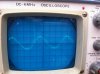
The attached photos are of the traces with the gain setting on Audacity (signal generator) at 2, 3 and 4 respectively, with no output load. The traces were substantially identical at the respective input levels for the left and right channels.

Do I understand this to show me that the amp goes to clipping under measurement conditions without distortion? If so, am I correct in understand this to tell me that the pre-driver stages off the amp appear to be working correctly. I think the theory here is that the pre-driver stages will be operating in a more or less normal way without load (ie passing current up to clipping) but that the output stages are effectively isolated by the absence of load?

Are D11,12 still in the frame?

Thanks, Jon
 

Attachments

  • IMG_0389.JPG
    IMG_0389.JPG
    81.5 KB · Views: 18
  • IMG_0390.JPG
    IMG_0390.JPG
    75.9 KB · Views: 20
  • IMG_0391.JPG
    IMG_0391.JPG
    69.4 KB · Views: 18
CRO traces look very good, however as per "Test and Alignment Procedures"
step #4, should try different frequencies ie, 2k, 20kHz, different frequency
gives different impedance.

D11, D12 are part of the over current protection circuit, this circuit will trigger
clipping as a protection mechansim.

Happy to wait on Craig to complete response.
 
I hadn't noticed that I was doing step#4 in the SM.

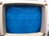
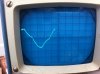
Previous traces were recorded at 2K Hz. I repeated at 20, 200 and 20K Hz. All traces remained clean sine up to gain setting 2 (as they did at 2K). But different things happened with the frequencies above this input level. See images (gain setting 4).
  • First image is at 20K Hz - waveform spread temporally
  • Second image is at 200Hz - less symmetrical clipping pattern
  • Third image is at 20Hz - waveform becomes asymmetrical
Is this the way clipping looks at different frequencies?
 

Attachments

  • IMG_0392.JPG
    IMG_0392.JPG
    68.4 KB · Views: 20
  • IMG_0393.JPG
    IMG_0393.JPG
    54.2 KB · Views: 19
  • IMG_0394.JPG
    IMG_0394.JPG
    63.6 KB · Views: 20
Will take a bit of time for me to digest those wave forms, some things to try maybe,
- bias OK?
- lift one leg of diodes D11, D12, ie remove protection circuit
- try 100Hz, ie try to identify where wave goes from clipped to horrible...

Do both channels have the same waveforms as post 116?
 
Maybe also check the RC on the speaker posts for bad solder joints as per SM troubleshooting Section C 7.
 
The two channels are practically identical in waveform response.

The RC on speaker posts look good (components and solder joints). The solder joints test good. Heavy solder and the posts have never come loose to stress the solder.

Bias remains good.

The wave form at 100Hz looks much like 200Hz. At 50Hz, the plateau slopes noticeably more than 200Hz. At 30-40Hz it becomes more like what we have at 20Hz.

I haven't tried D11,12. It will be fiddly to cut/reconnect. It would seem a little surprising if both channels were doing the same thing on account of D11,12.
 
I looked to google for some help. Maybe problem is with signal generator. Pic below shows how first and second harmonics combine, looks
a bit like the 20Hz trace.

Harmonics.JPG

Suggest check 20Hz output from signal generator at RCA, R1 or Q1b, whichever is easiest.
 
Back
Top Bottom