


MBuras
Restoration is an Addiction
Been working on a basket case Pioneer A-80 for a while. One amp board and outputs were completely trashed. Replaced the obvious and then tracked down a few more severely out of tolerance resistors. That channel is working just fine and begins clipping at 223wpc using direct mode, 1000hz signal and 8-ohm loads. On the other channel I replaced the exact same components to keep everything matched. Testing that channel it started clipping at around 30wpc. All amp board components and outputs check out ok.
Digging in with voltage measurements I found pin 16 & 17 feeding the output assembly are running over voltage (-79.5vdc when they should be -58vdc like the good channel). Those pins feed from a fast recovery common cathode dual diode D10 (CTU-21S). Both anode sides of that pin measure -79.5vdc. The common cathode side measures the appropriate -58vdc as does the filter capacitor further back in the circuit.
From these measurements I'm thinking D10 is bad.
Question #1 - Does anyone agree with this assessment?
Question #2 - Any suggestions for a replacement on the CTU-21S common cathode fast recover diode? I have a data sheet but not sure what the most important specs are. Also was hoping I might use 2 available UF4005 or similar diodes to fashion something instead of ordering one part.
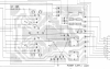
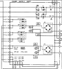
I've attached the board map and circuit diagram for the power supply in case they're needed.
Thanks for the help!
Mike
Digging in with voltage measurements I found pin 16 & 17 feeding the output assembly are running over voltage (-79.5vdc when they should be -58vdc like the good channel). Those pins feed from a fast recovery common cathode dual diode D10 (CTU-21S). Both anode sides of that pin measure -79.5vdc. The common cathode side measures the appropriate -58vdc as does the filter capacitor further back in the circuit.
From these measurements I'm thinking D10 is bad.
Question #1 - Does anyone agree with this assessment?
Question #2 - Any suggestions for a replacement on the CTU-21S common cathode fast recover diode? I have a data sheet but not sure what the most important specs are. Also was hoping I might use 2 available UF4005 or similar diodes to fashion something instead of ordering one part.
I've attached the board map and circuit diagram for the power supply in case they're needed.
Thanks for the help!
Mike

