MBuras
Restoration is an Addiction
I recently picked up a Pioneer A-80 on the cheap. It had a non-working channel with bad outputs and other various issues in that channel. After quite a bit of troubleshooting it's in running condition and received a full recap. Seeing as there's not much info on this receiver I figured I could contribute to the knowledge base by confirming some parts and providing notes on others.
These parts worked for me but YMMV. I didn't deviate too far from original values and some choices were made based on current part availability (Dec 2016) at Mouser. Hopefully I got the favored Pioneer forum format right.
AWH-124 Amp Board x 2:
AWH-124: C3: 330uF 50v CEA: 647-UPW1J471MHD 470uF 63v
AWH-124: C4: 330uF 50v CEA: 647-UPW1J471MHD 470uF 63v
AWH-124: C11: 220uF 100v CEA: 647-UPW2A331MHD 330uF 100v
AWH-124: C12: 220uF 100v CEA: 647-UPW2A331MHD 330uF 100v
AWH-124: C20: 470uF 25v CEXANP: 647-UES1E471MHM 470uF 25v
Notes:
Q2: 2SC2291 is a SIP-5 transistor with ecbce pinout
Q3: 2SC2259 is a SIP-5 transistor with bcecb pinout
GWF-155 EQ Board:
GWF-155: C13: 1000uF 25v ACH-445: 647-UPW1H102MHD 1000uF 50v
GWF-155: C14: 1000uF 25v ACH-445: 647-UPW1H102MHD 1000uF 50v
GWF-155: C15: 100uF 50v CEA: 647-UPW1H101MPD 100uF 50v
GWF-155: C16: 100uF 50v CEA: 647-UPW1H101MPD 100uF 50v
GWF-155: C25: 22uF 50v CEXANP: 647-UVP1H470MPD 47uF 50v
GWF-155: C26: 22uF 50v CEXANP: 647-UVP1H470MPD 47uF 50v
GWF-155: C29: 10uF 50v CEXA: 647-UPW1H100MDD 10uF 50v
GWF-155: C30: 10uF 50v CEXA: 647-UPW1H100MDD 10uF 50v
GWR-188 Regulator Board:
GWR-188: C101: 470uF 63v CEA: 647-UPW1J681MHD 680uF 63v
GWR-188: C102: 470uF 63v CEA: 647-UPW1J681MHD 680uF 63v
GWR-188: C103: 2.2uF 100v CEA: 647-UPW2A2R2MDD 2.2uF 100v
GWR-188: C104: 2.2uF 100v CEA: 647-UPW2A2R2MDD 2.2uF 100v
GWR-188: C107: 330uF 50v CEA: 647-UPW1H471MHD 470uF 50v
GWR-188: C108: 330uF 50v CEA: 647-UPW1H471MHD 470uF 50v
AWP-014 Output Board:
AWP-014: C1: 100uF 100v CEA: 647-UPW2A101MHD 100uF 100v
AWP-014: C2: 3.3uF 50v CEA: 505-MKS2B043301HJSSD 3.3uF 50v
AWP-014: C3: 470uF 6v CEA: 647-UPW1C471MPD 470uF 16v
AWP-014: C4: 10uF 50v CEA: 647-UPW1H100MDD 10uF 50v
AWP-014: C5: 33uF 16v CEA: 647-UPW1C330MDD 33uF 16v
AWP-014: C6: 1uF 100v CEA: 505-MKS21/100/5 1uF 100v
Notes:
Relay installed was Matsushita JC2aD-DC48. It was in fine condition but I did research anyway as to modern replacement options. Email to Omron revealed nothing currently available. Email to Mouser revealed nothing currently available. Internet research revealed Panasonic JC2AF-DC48V-F would work but is also discontinued. Currently (Dec 2016) available from an Ebay seller.
GWG-183 Tone Control Board:
GWG-183: C3: 2.2uF 50v CEANL: 505-MKS22.2/50/5 2.2uF 50v
GWG-183: C4: 2.2uF 50v CEANL: 505-MKS22.2/50/5 2.2uF 50v
GWG-183: C25: 1uF 50v CEANP: 505-MKS2B041001C00KS 1uF 50v
GWG-183: C26: 1uF 50v CEANP: 505-MKS2B041001C00KS 1uF 50v
GWG-183: C31: 22uF 16v CEANP: 647-UES1E330MPM 33uF 25v
GWG-183: C32: 22uF 16v CEANP: 647-UES1E330MPM 33uF 25v
GWG-183: C33: 1uF 50v CEANP: 505-MKS2B041001C00KS 1uF 50v
GWG-183: C34: 1uF 50v CEANP: 505-MKS2B041001C00KS 1uF 50v
GWS-488 Display Board:
GWS-488: C103: 100uF 25v CEA: 647-UPW1E101MED 100uf 25v
GWS-488: C104: 1uF 50v CEA: 505-MKS2B041001C00KS 1uF 50v
GWR-189 Power Supply Board:
GWR-189: C1: 1000uF 63v CEA: 647-UPW2A102MHD 1000uF 100v
GWR-189: C2: 1000uF 63v CEA: 647-UPW2A102MHD 1000uF 100v
GWR-189: C3: 12000uF 71v ACH-268: 661-ESMH800T153MB63T 15000uF 80v
GWR-189: C4: 12000uF 71v ACH-268: 661-ESMH800T153MB63T 15000uF 80v
GWR-189: C5: 10000uF 100v ACH-269: 661-EKMH101VRT103MB8 10000uF 100v
GWR-189: C6: 10000uF 100v ACH-269: 661-EKMH101VRT103MB8 10000uF 100v
Notes:
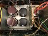
The United Chemi-Con filter capacitors chosen match the 40mm width of the originals which is important as the support cage cannot be easily modified to accept smaller diameter. They do vary in height so the original top foam block cannot be reused. These caps also match the exact pin spacing on the board, and have 5 leads like the originals, 3 dummy lugs to help with support.
Output Assembly A & B:
These will include both the components on the board as well as the heatsinked transistors attached. They do not have an assigned board number.
C103/C203: 0.47uF 100v CEANP: 505-MKS2.47/100/10 0.47uF 100v
D101/D201: 1S2471: 512-1N4148
Q1/Q2: 2SC3264: 2SC3264-ND [digikey]
Q3/Q4: 2SA1295: 2SA1295-ND [digikey]
Notes:
There are no modern replacements for the dual 0.22-ohm, 5-watt resistors [R105/R205]. Mine had one side open so I replaced with same value wirewounds and hand fashioned the linked resistors.
Tape/Mode Board:
RL1 had an Omron g2v-237p 12vdc small signal relay installed. It was in fine condition but I did research anyway into modern replacements. After exchanging a few emails with Mouser tech support they agreed the 653-G5V-2-DC12 would work as a replacement. It is currently available (Dec 2016).
IMHO this is a pretty great integrated when restored but please note that I'm not a huge fan of the warmer sounds in the 1970's. I enjoy the more accurate, but not harsh, sound found in the late 70's/early 80's equipment. And of course it has gobs of power!
These parts worked for me but YMMV. I didn't deviate too far from original values and some choices were made based on current part availability (Dec 2016) at Mouser. Hopefully I got the favored Pioneer forum format right.
AWH-124 Amp Board x 2:
AWH-124: C3: 330uF 50v CEA: 647-UPW1J471MHD 470uF 63v
AWH-124: C4: 330uF 50v CEA: 647-UPW1J471MHD 470uF 63v
AWH-124: C11: 220uF 100v CEA: 647-UPW2A331MHD 330uF 100v
AWH-124: C12: 220uF 100v CEA: 647-UPW2A331MHD 330uF 100v
AWH-124: C20: 470uF 25v CEXANP: 647-UES1E471MHM 470uF 25v
Notes:
Q2: 2SC2291 is a SIP-5 transistor with ecbce pinout
Q3: 2SC2259 is a SIP-5 transistor with bcecb pinout
GWF-155 EQ Board:
GWF-155: C13: 1000uF 25v ACH-445: 647-UPW1H102MHD 1000uF 50v
GWF-155: C14: 1000uF 25v ACH-445: 647-UPW1H102MHD 1000uF 50v
GWF-155: C15: 100uF 50v CEA: 647-UPW1H101MPD 100uF 50v
GWF-155: C16: 100uF 50v CEA: 647-UPW1H101MPD 100uF 50v
GWF-155: C25: 22uF 50v CEXANP: 647-UVP1H470MPD 47uF 50v
GWF-155: C26: 22uF 50v CEXANP: 647-UVP1H470MPD 47uF 50v
GWF-155: C29: 10uF 50v CEXA: 647-UPW1H100MDD 10uF 50v
GWF-155: C30: 10uF 50v CEXA: 647-UPW1H100MDD 10uF 50v
GWR-188 Regulator Board:
GWR-188: C101: 470uF 63v CEA: 647-UPW1J681MHD 680uF 63v
GWR-188: C102: 470uF 63v CEA: 647-UPW1J681MHD 680uF 63v
GWR-188: C103: 2.2uF 100v CEA: 647-UPW2A2R2MDD 2.2uF 100v
GWR-188: C104: 2.2uF 100v CEA: 647-UPW2A2R2MDD 2.2uF 100v
GWR-188: C107: 330uF 50v CEA: 647-UPW1H471MHD 470uF 50v
GWR-188: C108: 330uF 50v CEA: 647-UPW1H471MHD 470uF 50v
AWP-014 Output Board:
AWP-014: C1: 100uF 100v CEA: 647-UPW2A101MHD 100uF 100v
AWP-014: C2: 3.3uF 50v CEA: 505-MKS2B043301HJSSD 3.3uF 50v
AWP-014: C3: 470uF 6v CEA: 647-UPW1C471MPD 470uF 16v
AWP-014: C4: 10uF 50v CEA: 647-UPW1H100MDD 10uF 50v
AWP-014: C5: 33uF 16v CEA: 647-UPW1C330MDD 33uF 16v
AWP-014: C6: 1uF 100v CEA: 505-MKS21/100/5 1uF 100v
Notes:
Relay installed was Matsushita JC2aD-DC48. It was in fine condition but I did research anyway as to modern replacement options. Email to Omron revealed nothing currently available. Email to Mouser revealed nothing currently available. Internet research revealed Panasonic JC2AF-DC48V-F would work but is also discontinued. Currently (Dec 2016) available from an Ebay seller.
GWG-183 Tone Control Board:
GWG-183: C3: 2.2uF 50v CEANL: 505-MKS22.2/50/5 2.2uF 50v
GWG-183: C4: 2.2uF 50v CEANL: 505-MKS22.2/50/5 2.2uF 50v
GWG-183: C25: 1uF 50v CEANP: 505-MKS2B041001C00KS 1uF 50v
GWG-183: C26: 1uF 50v CEANP: 505-MKS2B041001C00KS 1uF 50v
GWG-183: C31: 22uF 16v CEANP: 647-UES1E330MPM 33uF 25v
GWG-183: C32: 22uF 16v CEANP: 647-UES1E330MPM 33uF 25v
GWG-183: C33: 1uF 50v CEANP: 505-MKS2B041001C00KS 1uF 50v
GWG-183: C34: 1uF 50v CEANP: 505-MKS2B041001C00KS 1uF 50v
GWS-488 Display Board:
GWS-488: C103: 100uF 25v CEA: 647-UPW1E101MED 100uf 25v
GWS-488: C104: 1uF 50v CEA: 505-MKS2B041001C00KS 1uF 50v
GWR-189 Power Supply Board:
GWR-189: C1: 1000uF 63v CEA: 647-UPW2A102MHD 1000uF 100v
GWR-189: C2: 1000uF 63v CEA: 647-UPW2A102MHD 1000uF 100v
GWR-189: C3: 12000uF 71v ACH-268: 661-ESMH800T153MB63T 15000uF 80v
GWR-189: C4: 12000uF 71v ACH-268: 661-ESMH800T153MB63T 15000uF 80v
GWR-189: C5: 10000uF 100v ACH-269: 661-EKMH101VRT103MB8 10000uF 100v
GWR-189: C6: 10000uF 100v ACH-269: 661-EKMH101VRT103MB8 10000uF 100v
Notes:
The United Chemi-Con filter capacitors chosen match the 40mm width of the originals which is important as the support cage cannot be easily modified to accept smaller diameter. They do vary in height so the original top foam block cannot be reused. These caps also match the exact pin spacing on the board, and have 5 leads like the originals, 3 dummy lugs to help with support.
Output Assembly A & B:
These will include both the components on the board as well as the heatsinked transistors attached. They do not have an assigned board number.
C103/C203: 0.47uF 100v CEANP: 505-MKS2.47/100/10 0.47uF 100v
D101/D201: 1S2471: 512-1N4148
Q1/Q2: 2SC3264: 2SC3264-ND [digikey]
Q3/Q4: 2SA1295: 2SA1295-ND [digikey]
Notes:
There are no modern replacements for the dual 0.22-ohm, 5-watt resistors [R105/R205]. Mine had one side open so I replaced with same value wirewounds and hand fashioned the linked resistors.
Tape/Mode Board:
RL1 had an Omron g2v-237p 12vdc small signal relay installed. It was in fine condition but I did research anyway into modern replacements. After exchanging a few emails with Mouser tech support they agreed the 653-G5V-2-DC12 would work as a replacement. It is currently available (Dec 2016).
IMHO this is a pretty great integrated when restored but please note that I'm not a huge fan of the warmer sounds in the 1970's. I enjoy the more accurate, but not harsh, sound found in the late 70's/early 80's equipment. And of course it has gobs of power!